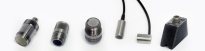
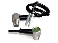
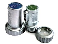
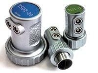
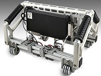
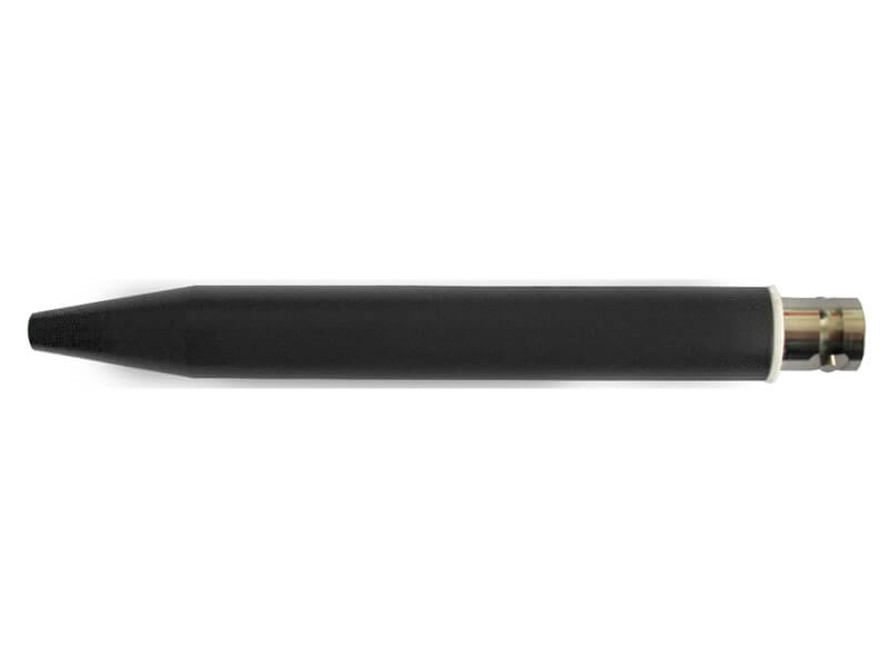
OKOSCAN UT 73HS PICKUP
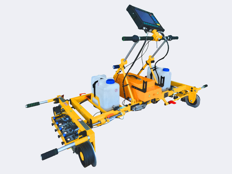
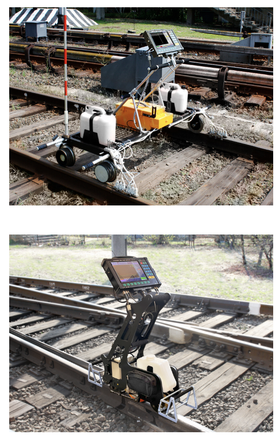
The ultrasonic rail flaw detector UDS2-73 RSUI is designed for continuous mechanized testing of the rail track including turnouts (crossings, frogs) at a speed of up to 5 km/h.
The ultrasonic rail flaw detector UDS2-73 RSUI is designed for continuous mechanized testing of the rail track including turnouts (crossings, frogs) at a speed of up to 5 km/h.
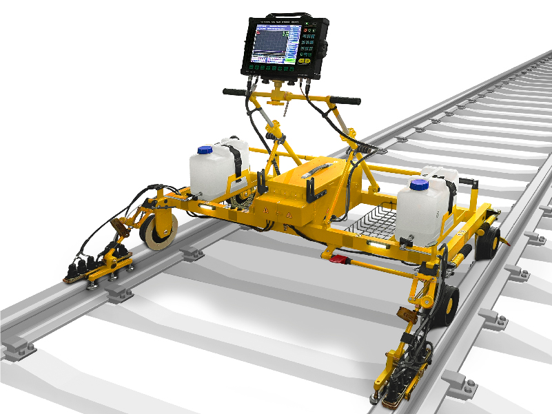
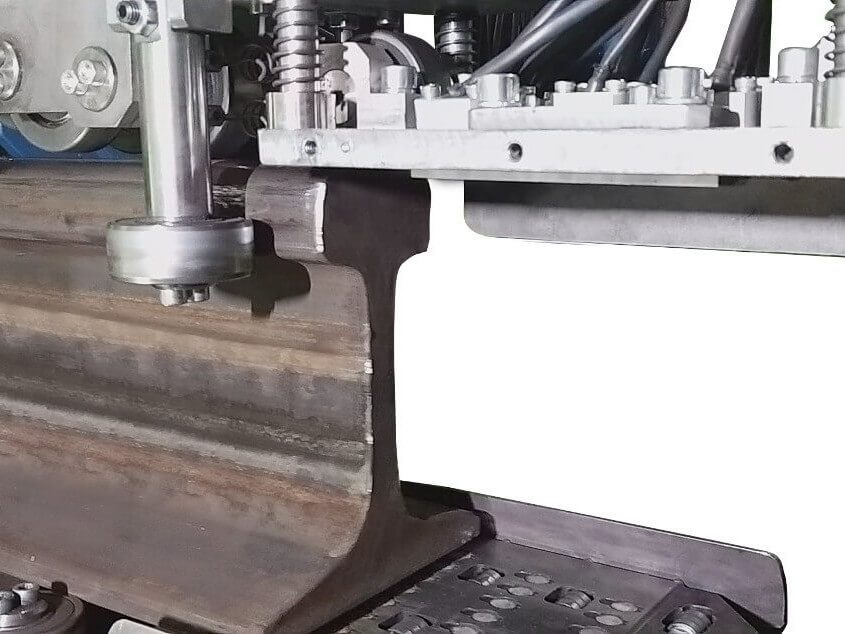
The flaw detector is intended for defects detection in both rails along the running surface and rail cross-section, except for the rail base blades using flaw detection trolley during complete testing, and for the confirmatory testing of separate rail cross-sections and welded joints by means of manual probes.
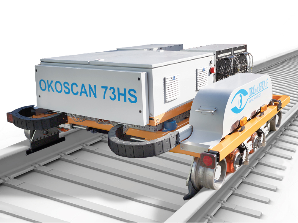
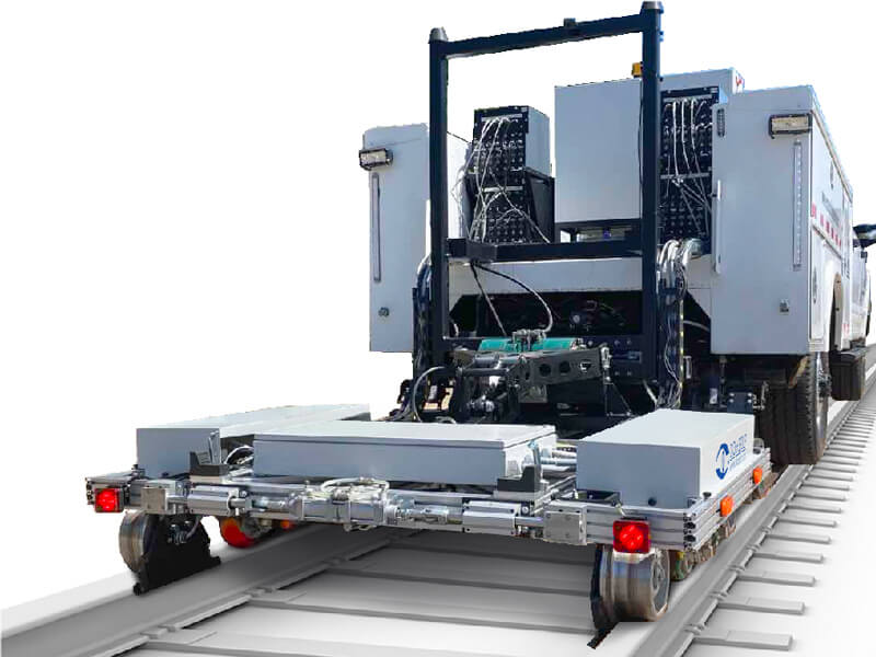
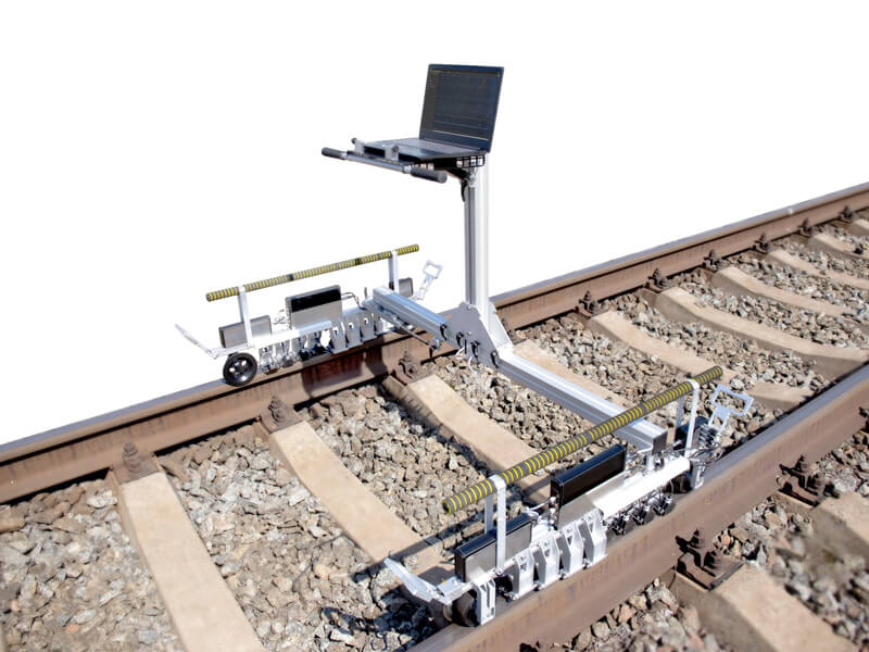
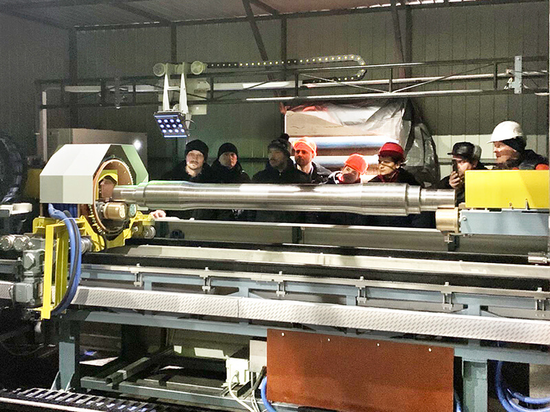
The OKOSCAN 73HS System is intended for automated high-speed testing of rails laid down in a track.
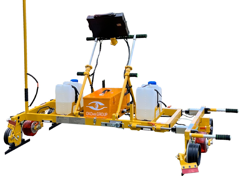
Ultrasonic dual-rail flaw detector UDS2-73 SL for ultrasonic inspection of standard profile rails and tram rails
The ultrasonic rail flaw detector UDS2-73 RSUI is designed for continuous mechanized testing of the rail track including turnouts (crossings, frogs) at a speed of up to 5 km/h.
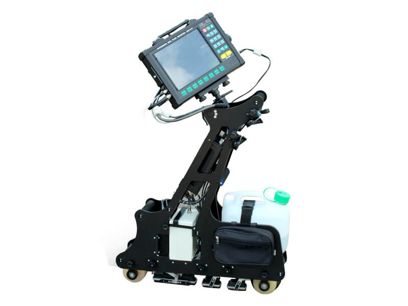
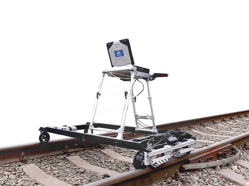
Ultrasonic single-rail flaw detector UDS2-77 SC is a manually driven cart designed for autonomous inspection of one streetcar line with rails of "groove" type and standard profile rails during .
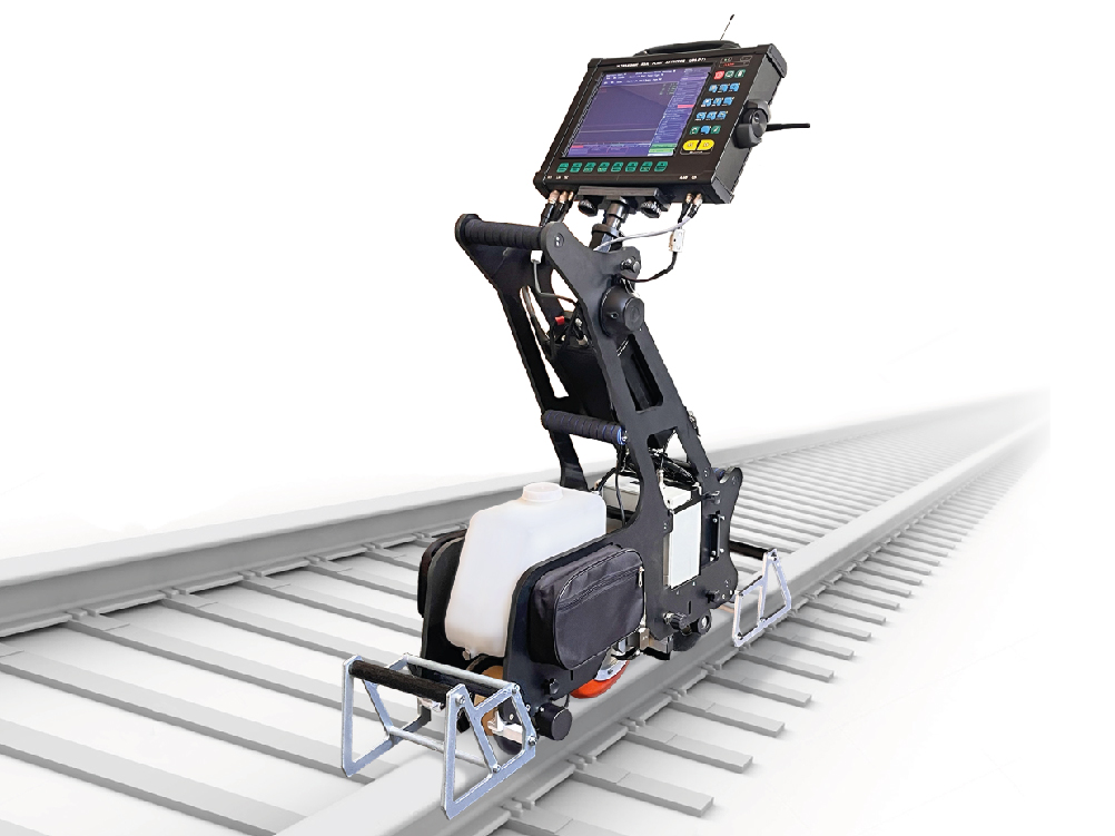
UDS2-77 ultrasonic single rail flaw detector is a mechanized trolley intended for the inspection of one rail line. The flaw detector utilizes a unique scanning scheme that allows testing the entire rail section, except for foot flanges, by pulse echo, echo-shadow and echo-image techniques.
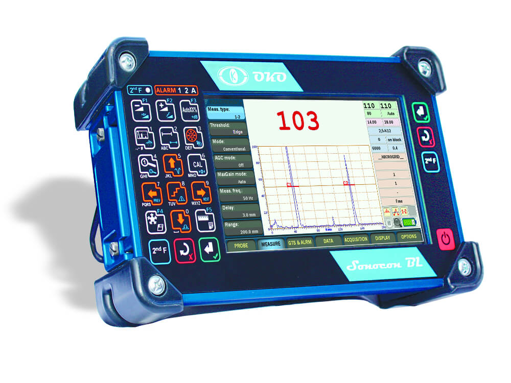
Sonocon BL belongs to the latest generation of portable UT instruments. Using a high-end electronics and having a richest set of modes and software features it can solve any task that can be sold with portable UT.
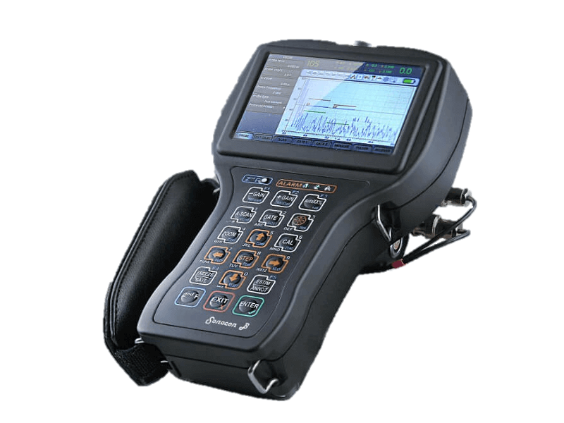
The Sonocon B belongs to the next generation of portable UT instruments. Using high-end electronics and having the richest set of modes and software features, it can solve any task that can be solved with a portable UT device.
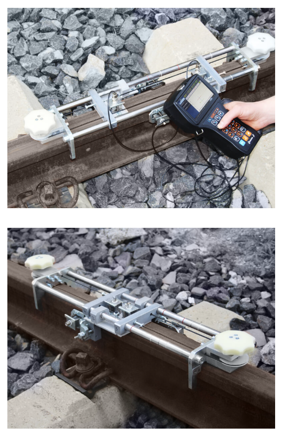
USR-01 Set is intended for ultrasonic inspection of aluminothermic welded rail joints in accordance with EN14730-1 requirements. The USR-01 Set can be used for inspection of joints welded by the electrocontact method, for secondary rail track inspection based on the results of mechanized and quick systems of ultrasonic testing, as well as for pre-weld inspection of end sections of new and used rails before welding them at rail welding enterprises or in tracks.
The ОКО-22М-UT ultrasonic flaw detector is a standalone electronic unit and is intended for application in high-performance automated multi-channel NDT Systems, transportable systems (mechanized NDT systems) or for manual testing. Available in several flaw detector models that are different in number of channels and in a volume of built-in functions for results processing.
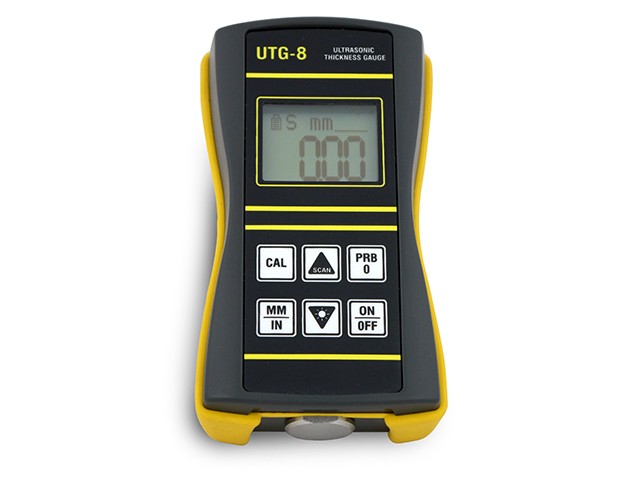
The UTG-8 is a precision Ultrasonic thickness gauge. Based on the same operating principles as SONAR.
The basic task of the eddy current nondestructive testing of railroad is to reveal head check cracking and to evaluate a damage depth in the gauge side of the rail head and the rail head running surface.
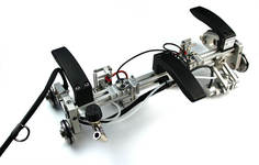
ETS2-73 is the mechanized scanning device for the manual testing by eddy-current method for presence of the surface cracks.

«Thickness Gauge +» is an ultrasonic version of Sonocon B flaw detector. It is a multifunctional next generation precise thickness gauge which combines the functionality of a traditional thickness gauge and corrosion monitor.
The UTG-8 is a precision Ultrasonic thickness gauge. Based on the same operating principles as SONAR.
TOFD 2.10 PRO Ultrasonic scanning device implements the mechanized testing of butt - welded joints of flat surfaces and pipes of medium and large diameters (with a minimum external diameter of 600 mm) and a thickness from 6 to 75 mm. Using the TOFD 2.10 PRO defects such as discontinuities, lack of fusions, cracks, porosity and slag shots can be detected and also their sizes with their coordinate dimensioning to the testing objects can be determined.
-
-
-
-
-
-
-
-
-
-
-
-
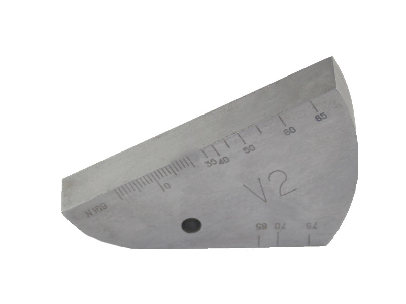
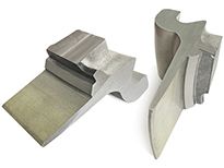
V2 Calibration Block is designed for verification of the ultrasonic flaw detectors used in the course of welded joints quality control by the UT method. It is DSTU 4002-2000 (ISO 7963, В.S.2704) compliant.

V1 Calibration Block is designed for verification of the ultrasonic flaw detectors used in the course of welded joints quality control by the UT method. It is DSTU 4002-2000 (ISO 2400, DIN 54120, B.S. 2704) compliant.
SC Block is designed for shear ultrasonic waves sensitivity calibration. It is presented with the engineering plastic storage case. The SC Block is ASTM E164 and BRR/AWS standards compliant.
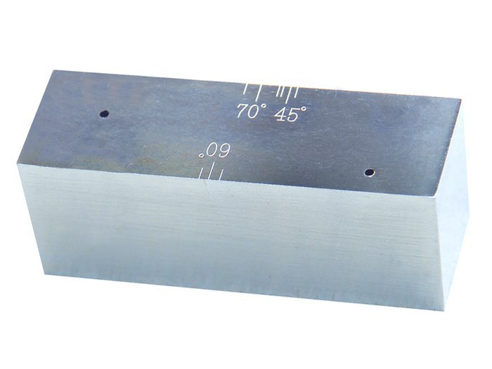
AS2083 Calibration Block no. 2, IOW Type 2 Block is designed for the beam profile measurement and probe angle of the angle beam transducers (also called Beam Calibration Block). The Block is Australian Standard AS2083 and British Standard 2704* compliant.
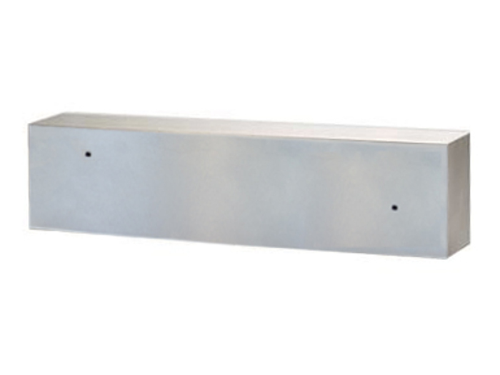
The Notched Calibration Block (having plane angular reflectors) is designed for setting up the scan duration and sensitivity of flaw detectors used with the single crystal angle beam probes during the testing of the plate and tube products.
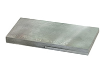
KMT-176 M2 Set of the Ultrasonic Plane-Parallel Thickness Standards (KUSOT-180) is designed for certification and primary checking of the contact ultrasonic thickness gauges at the manufacturing site with the thickness range of 0.6-300 mm in steel and 1-300 mm in duraluminum, as well as for the periodic verification of these thickness gauges.
Step Calibration Block is used for tuning and setting of the ultrasonic thickness gauges.
Over few decades TOFD method is widely used for fast and reliable UT of welded joints. TOFD offers great accuracy for measuring the critical size of crack-like-defects. The accuracy of better than ±1mm can be obtained in a wide range of material thickness.
Over few decades TOFD method is widely used for fast and reliable UT of welded joints. TOFD offers great accuracy for measuring the critical size of crack-like-defects. The accuracy of better than ±1mm can be obtained in a wide range of material thickness.
-
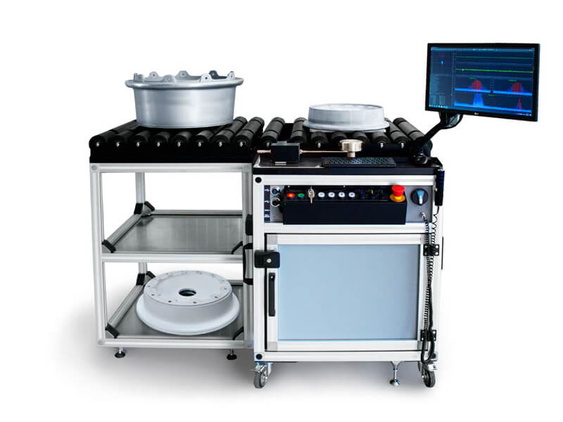
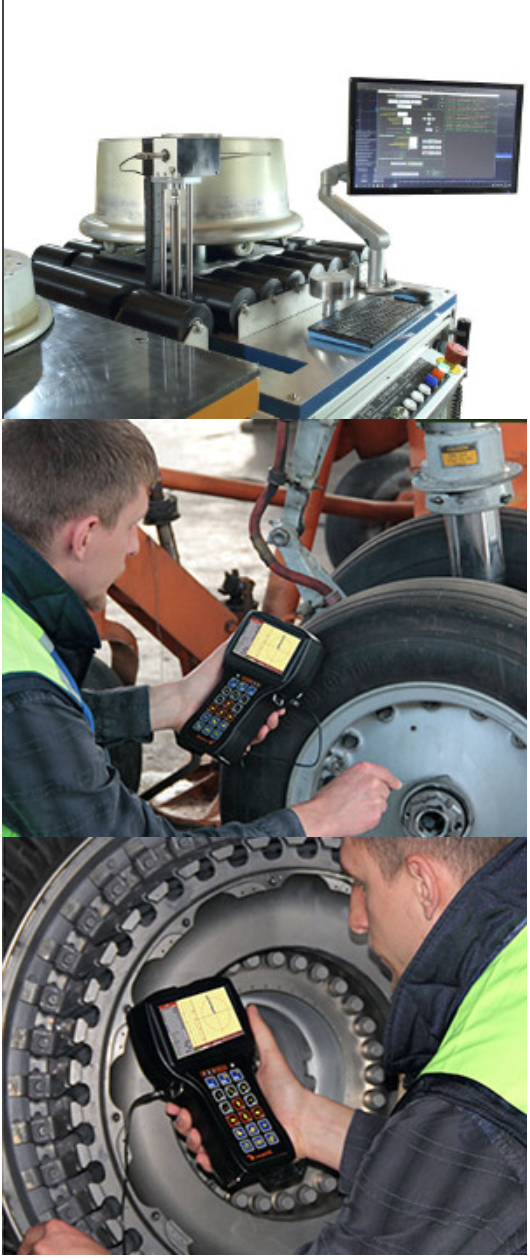
SMARTSCAN Aircraft Wheel Inspection System is intended for testing of main and nose wheels of aircrafts of various world manufacturers such as Messier - Bugatti, Goodrich, Honeywell, Maggitt and others.
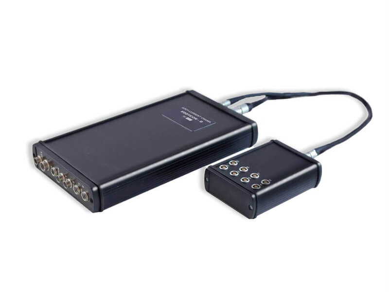
The EDDYCON D universal multi-channel eddy current flaw detector is designed to solve a wide range of tasks of eddy current flaw detection.
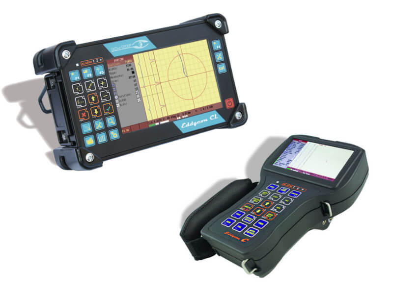
The EDDYCON C&CL portable eddy current flaw detectors are flagships in our eddy current instrument family. They combine the best features of earlier predecessors, being furnished with 4.3" (Eddycon C) or 7.2" (Eddycon CL) display and functional buttons for immediate access to any menu of the instrument, which would meet requirements of the most demanding user.
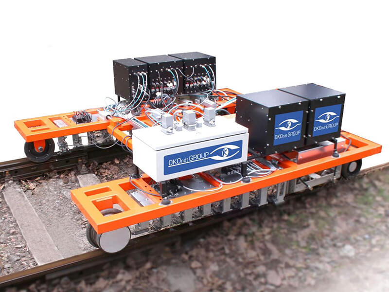
The OKOSCAN 73HS System is intended for automated high-speed testing of rail in service.
ETS2-77 is the mechanized scanning device for the manual testing by eddy-current method for presence of the surface cracks.
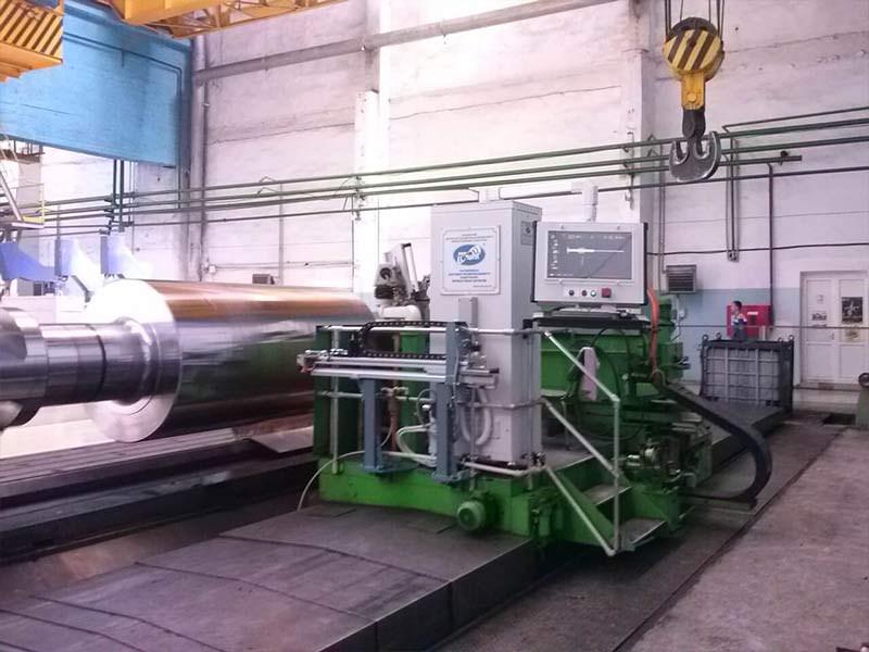
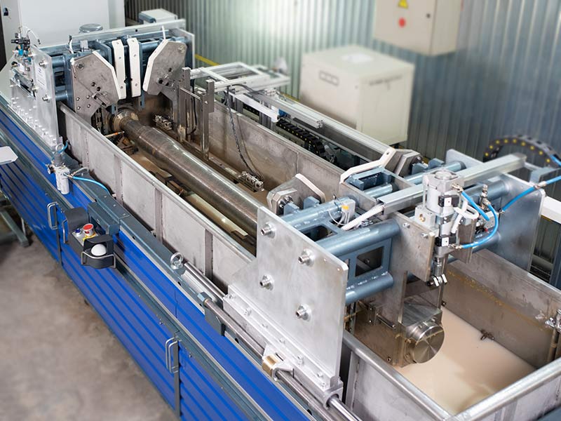
EDC RAIL 5065 Eddy-Current Testing Machine is designed for automated non-destructive testing of railway rails by eddy-current method in the course of their manufacturing. The presence of surface defects such as outer surface cracks of the rail heads, flutings and railway rails base of R50, R65, R65K, 60E1, UIC60 types is tested according to DIN EN 13674-1-2017.
-

-
-
-
-
-
-
-
-
-
-
-
-
-
-
-
-
-
-
-
-
-
-
-

-
-
-
-
-
-
The ОКО-22М-EMA ultrasonic flaw detector is an independent electronic device and is designed for application in stationary high-performance systems (automated multi-channel NDT Systems), transportable systems (mechanized NDT systems) or for manual testing.
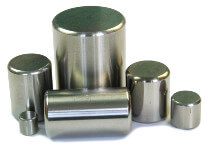
Work rolls is the main tool of the rolling manufacture, which ensures due quality of the finished rolled products. Uninterrupted operation of the powerful rolling mill and high-quality finished products depend a lot on the mill rolls surface condition and their quality
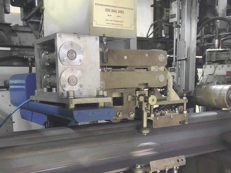
Eddy current testing System of rails EDC RAIL 5065
allows to perform an automated eddy current testing for presence of the
surface defects. Main defect types that are subject to testing by the
System are the surface defects such as cracks, laps, hairline cracks
located on the outer surface of the rail head and rail shoe of 49Е1,
60Е1, UIC60 rail types etc in accordance with EN 13674–1–2017
requirements.
Nowadays, the railway transport is one of the major means for transportation of goods and passengers. To assure the safety of cargo traffic it is crucial to use high-quality elements of the railway car wheelsets which are highly succumbed to a dynamic loading in-service. That is why the quality control during production of one of the wheelset elements, namely axles, is critical.
Since early 2010, the OKOndt
Group company has been conducting scientific-and-research and
experimental-and-design works in the field of automation of the
non-destructive testing methods for the railway wheelset elements
testing. Implementation of the developed Systems for automated
ultrasonic testing AUTS Axle-4 OS-4 and mechanized magnetic particle testing OS-38
(hereinafter – the Systems) enabled the enterprises of PJSC «INTERPIPE
NTRP» and PJSC Lugcentrokuz a. S. Monyatovsky to promote their product
at the world market and successfully certify their quality labs for
compliance with requirements of European and American regulatory
documents.
Ultrasonic Testing
Railway tracks are inspected by ultrasonic high frequency waves, usually the ultrasonic waves with a frequency of 2 to 5 MHz are used to inspect rails.
Since the defects in rails have different nature (direction of development, manufacturing defects, operational defects), different angles of ultrasound input into the rail and various sounding schemes and testing methods are used, for example: echo method, echo-shadow method, tandem methods.
Besides that, the manufacturers of ultrasonic rail testing equipment for the effective and efficient defects detection implement different types of data output to the screen, for example: A-scan, B-scan and their various combinations.
The variety of testing methods and sounding schemes, as well as various types of data visualization make it possible to effectively and with great probability detect the defects at different stages of their development.
Eddy-current testing of rails
In the rails head acting surface, as well as on the rail head running surface the quenching cracks may be developed in the process of the rails exploitation. This type of defect appears on the rail surface and develops to the depth with some time.
Timely detected and assessed defect depth in the rail head and on the head running surface allow to extend the service resource by the rail profile recovery with the grinding machines.
The eddy-current method application in this case is justified not only by a possibility to detect flaws but also by their assessment.

At the moment various rail testing technologies are used in ultrasonic rail inspection, which in turn require the participation of a person to interpret the results of their test. Different regions and countries apply their own approach to ultrasonic rail testing. There are three basic approaches to rail inspection:
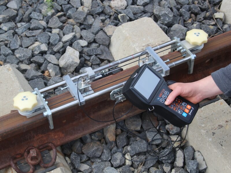
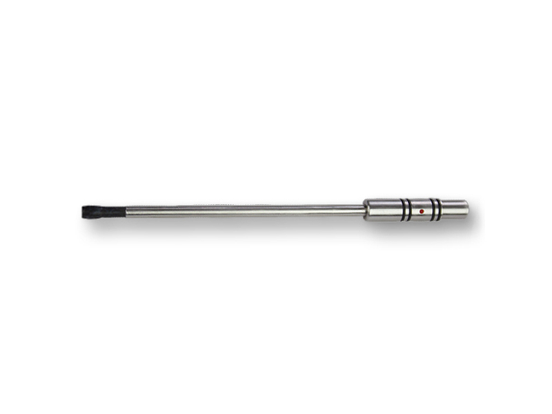
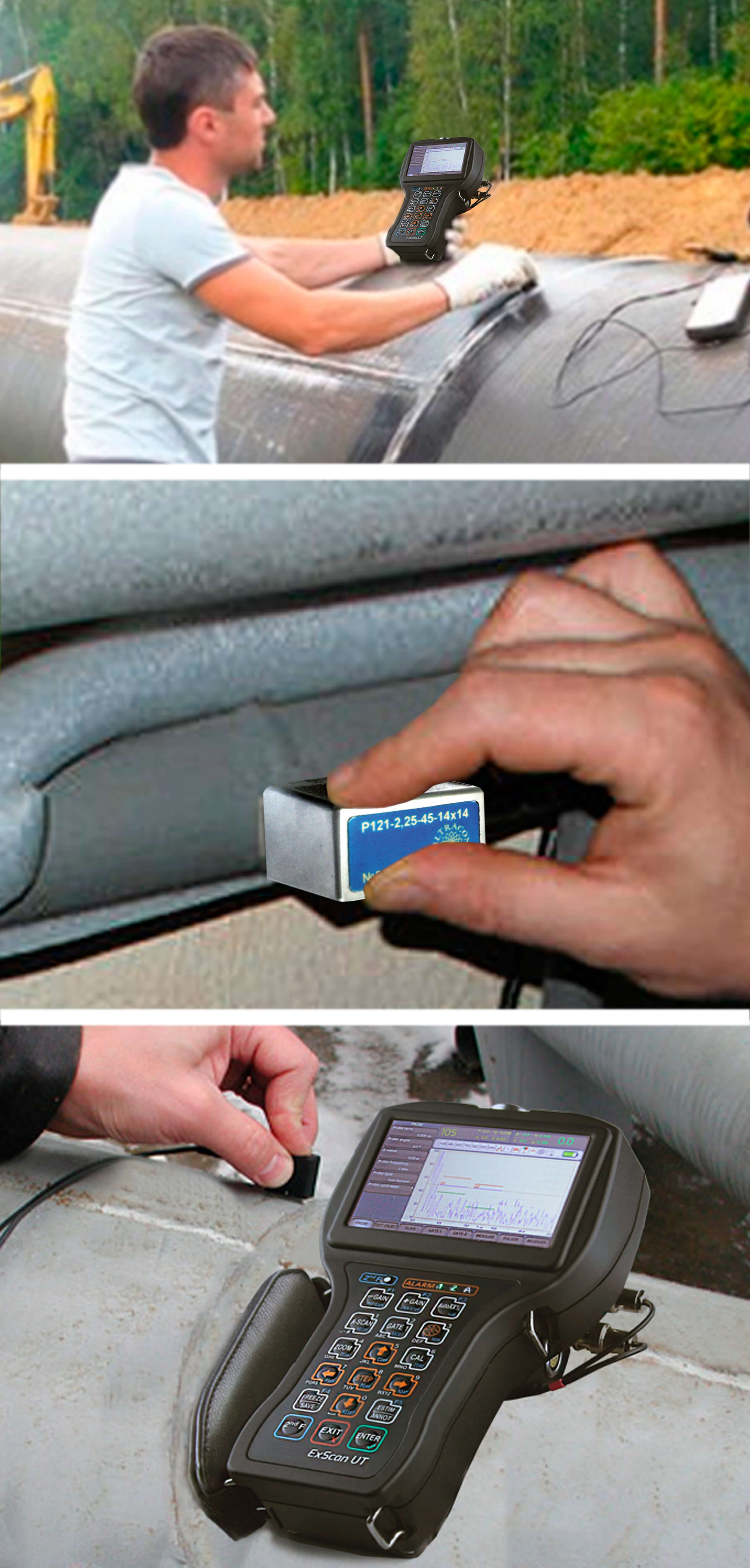
Manual inspection and ultrasonic testing of rails implies using a hand-held ultrasonic flaw detector (Sonocon B) plus a set of ultrasonic transducers and a special scanning device (USR-01) with the help of which it is possible to carry out a secondary testing of railroad tracks laid, according to the results of mechanized inspection by ultrasonic or combined ultrasonic rail flaw detectors and flaw monitoring and detecting railcars, as well as for the pre-weld inspection of the end sections of new and used rails before welding them at rail welding enterprises or monitoring joints welded by electrocontact or aluminothermic method.
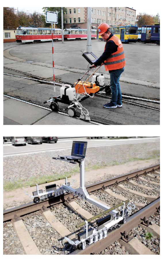
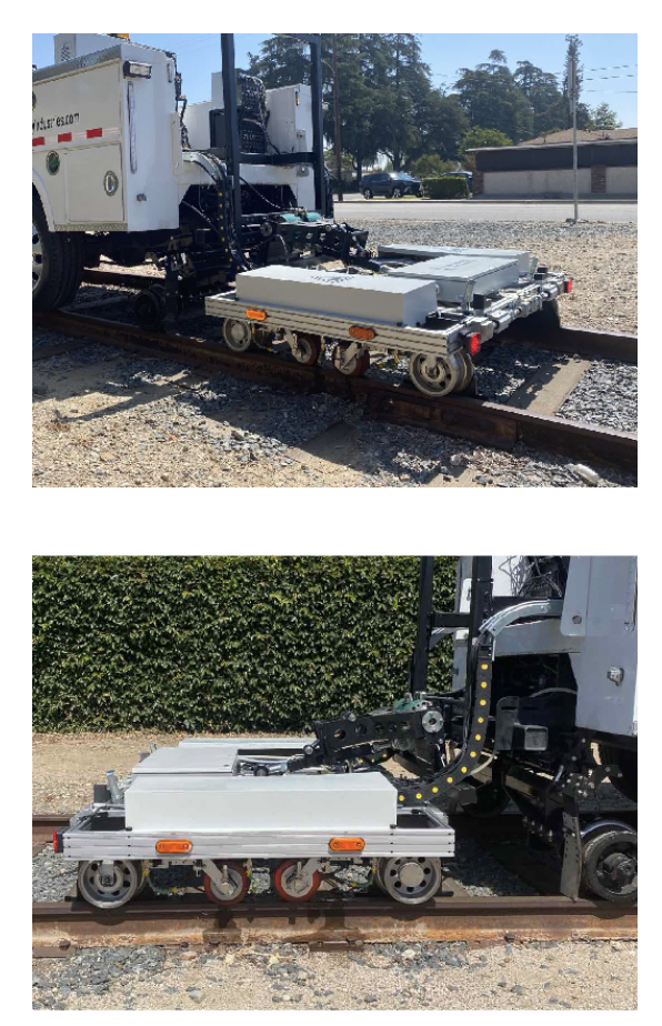
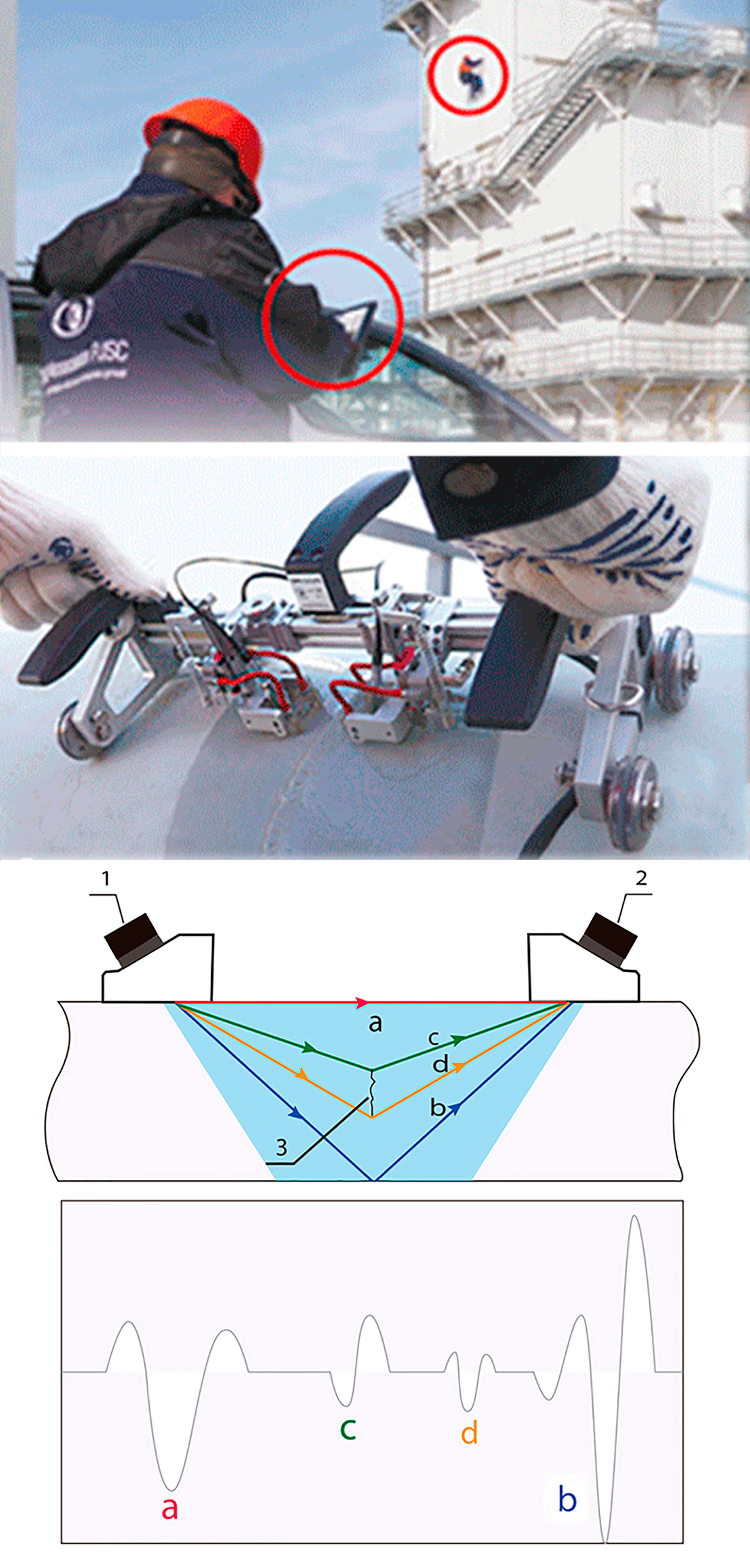
This type of testing involves the use of mechanized trolleys, which are moved by operator. There are two types of trolleys exist:
Such mechanized trolleys house the electronic equipment and transducer blocks, which in turn implement various rail inspection schemes.
Mechanized ultrasonic rail testers allow to carry out:
Mechanized eddy-current flaw detectors allow to carry out:
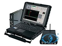
This technology lies in the fact that the ultrasonic testing of railway tracks is carried out by means of high-speed transport systems (vehicle, wagon or rail car) without stopping along the assigned route; this allows you to inspect areas exceeding 100 km per shift.
After that, the collected data is sent and analyzed in a remote location. Once the data has been analyzed and potentially dangerous sections of rail are revealed, the report is sent to the operators who are conducting confirmatory checks with the help of manual or mechanized rail flaw detectors.
The extensive range of OKOndt GROUP™ NDT equipment includes the OKOSCAN UT73HS - High-Speed Rails Testing System. This ultrasonic testing vehicle provides testing at a maximum speed of 40 km/h (25 miles) and can detect all types of crucial defects.
Eddy current non-destructive testing method is of paramount importance for technical diagnostics of aircraft parts.
The eddy current method has a number of advantages as compared to other methods, in terms of the costs of NDT equipment and consumables. This method is distinguished by high productivity, high reliability of testing and does not impose specific requirements on the quality or roughness of surface to be tested. Testing can be performed even without removing the coating or scaling.
The eddy current method is used for testing wings (fatigue cracks on the inside of wing boxes), bodies, wheel discs, engine parts (mainly - engine blades), rotors, axes, fasteners and holes (flaws in rivets, with the latter remaining in place), landing gears made of high-strength steel.
Eddy current testing is possible both at the stage of production of aircraft, helicopters or other aircraft equipment, and during on-site maintenance.
On-site maintenance of aircraft includes:
High-frequency eddy current testing | Low-frequency eddy current testing |
| (detection of fatigue or corrosion surface flaws) | (detection of fatigue or corrosion sub-surface flaws) |
| airframe parts (wings, bodies) | cracks under skin |
| landing gears (wheel discs) | cracks under repair patch |
| propellers | cracks under sealant |
| control units | cracks inside riveted joints |
| riveted and bolted joints | flaws under rivet head |
| engine blades |
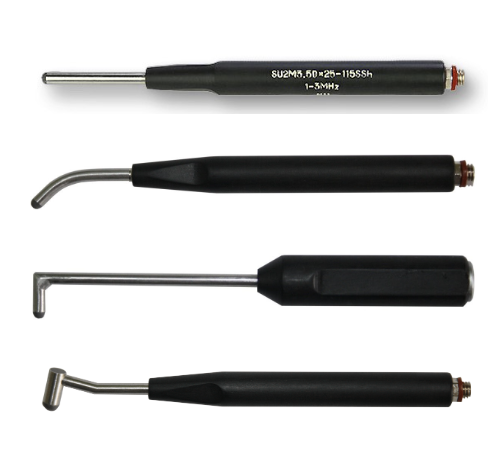
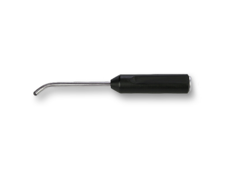
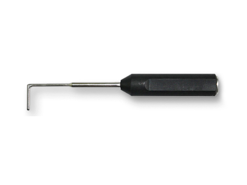
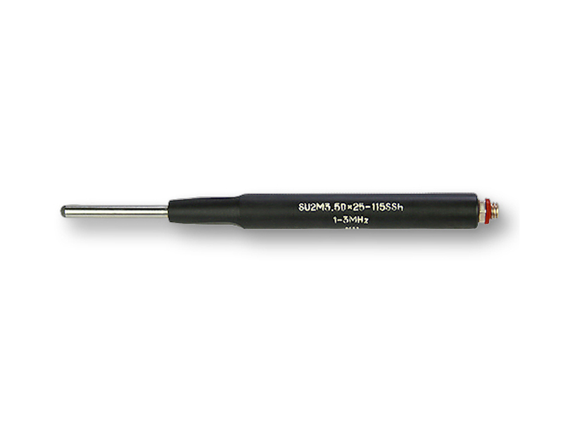
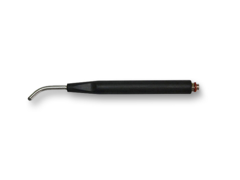
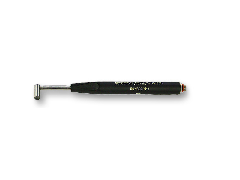
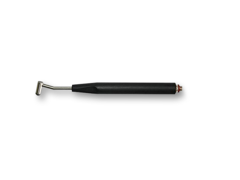
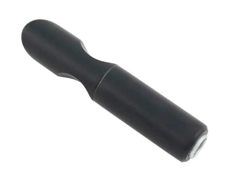
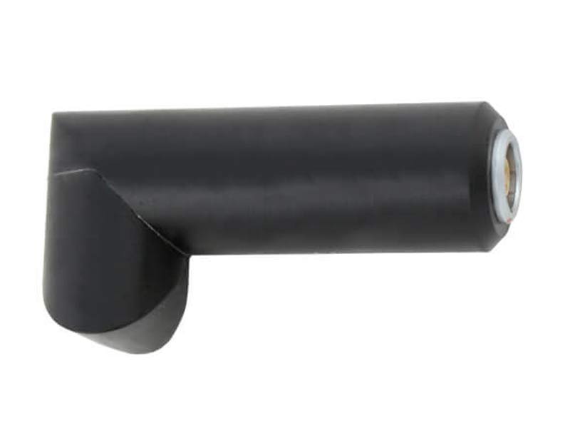
This task has been successfully solved thanks to high-frequency NDT technologies which are based on the use of relatively high operating frequencies (over 1 MHz). In aluminum alloy parts, cracks can be detected at a depth over 0.2 mm, with a minimum length of 2 mm and width of 0.1 mm. In titanium alloy, austenitic and ferritic steel parts, cracks can be detected at a depth over 0.5 mm, with a minimum length of 2 mm and width of 0.1 mm. Eddy current flaw detectors are provided with pencil-type or L-shaped probes, as well as with special-purpose probes for testing blades and hole edges.

An essential advantage of the eddy current non-destructive testing method is the possibility to detect flaws of fatigue and corrosion origin in the inner layers of multilayer structures, even without removing the fasteners and without disassembling the structures. This facilitates an effective use of the eddy current method not only during the repair of aircraft, when it is possible to remove the fasteners, but directly during tests or on-site maintenance.
Based on the new design of eddy current probes, fundamentally new technologies and means for recognizing the hidden flaws in integral multilayer aircraft structures have been created, particularly, for detecting the flaws under aircraft skin at low frequencies.
Test objects
Fasteners, integral multilayer structures, repair patch in the middle of aircraft wing, shock strut pistons, riveted joints, inside parts of wing boxes, skin-stringer interface.
Another important task that can be successfully solved with the eddy current testing method is the detection of the surface defects in the holes and countersinks. These areas can be effectively and efficiently tested using rotary eddy current scanners equipped with special ECPs (reflection type) of different diameters.

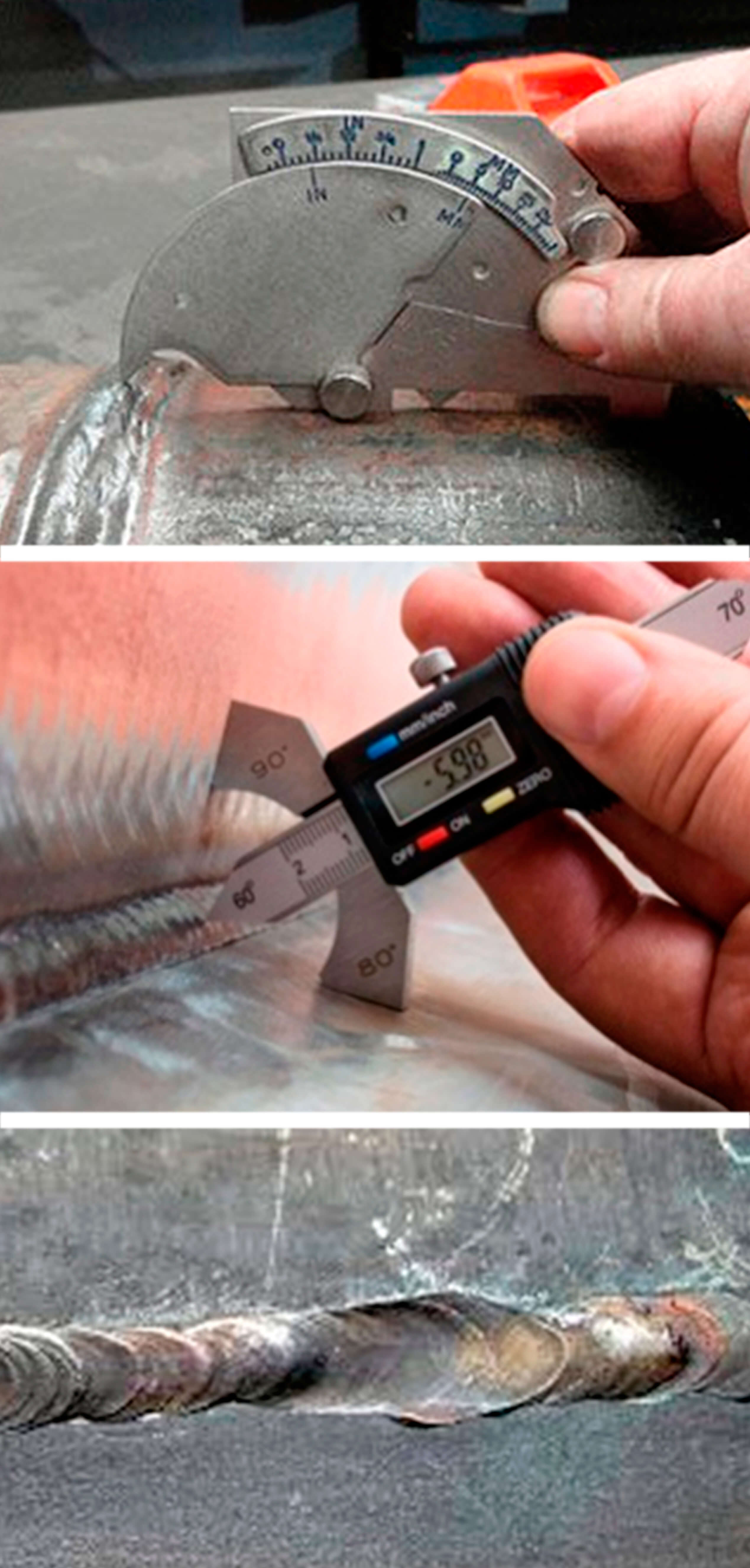
This method combines a visual inspection and measurement of the geometrical parameters of welds to check their compliance with the required values. Before testing, the welds should be cleaned from scale, slag and metal splashes. After that, the surface should be treated with alcohol, or etched using a 10% solution of nitric acid. As a tool for this type of testing, a 5 or 10-power magnifier, as well as lighting devices and measuring instruments (ruler, calipers, templates) are normally used to verify both the weld and defect sizes. Despite its apparent simplicity, this type of testing is very effective and is prior to other methods. If the flaws are detected already at this stage, the weld is considered as rejected, and further testing is not performed. An obvious disadvantage of this method is the impossibility to detect the majority of hidden defects and the subjectivity of evaluation methods, which requires a lot of experience from NDT inspector.
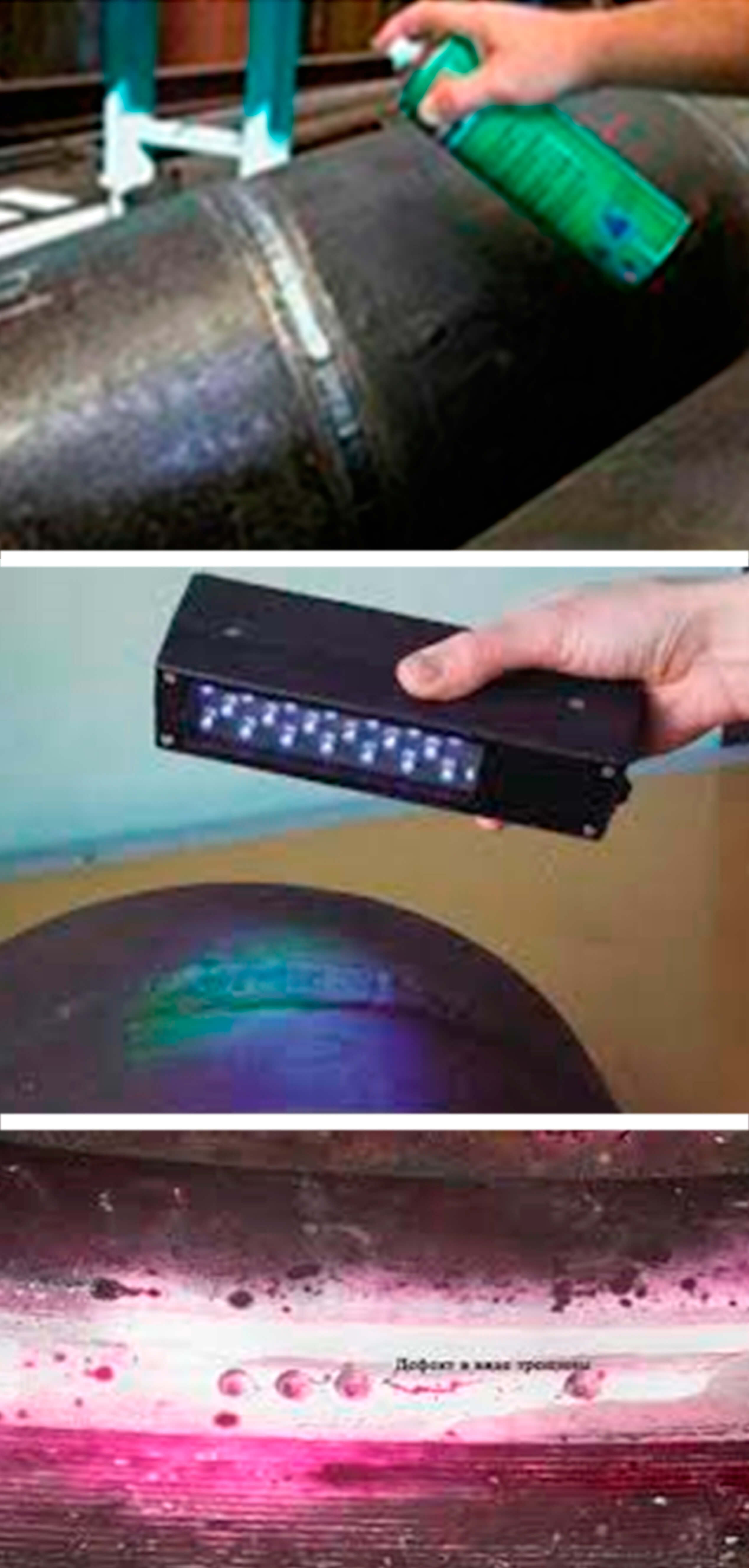
This method is based on the ability of the liquid to penetrate into and fill the smallest capillary channels that are essentially made by weld defects. Such defects include pores and cracks that break the surface of the material. The rate and depth of penetration of the liquid depends on the radius of the capillary and the wettability of the liquid. Thus, the penetrant method is very effective for detecting surface flaws. To increase its efficiency, the so-called penetrants are used which can penetrate deep into the capillary due to their small surface tension. Their bright color makes them noticeable, which facilitates the detection of a defect. A penetrant testing kit normally includes a penetrant; cleanser for thorough cleaning of the surface before testing; developer for extracting the penetrant from the defect and creating an indicator pattern on a contrast background, using which it is possible to see the size and form of the defect. This method of testing is similar to the visual one, since it presupposes visual inspection of the weld, therefore, has the same disadvantages.
UT is one of the most common methods, because it ensures an accurate detection of hidden flaws located inside the weld. The method is based on the use of ultrasonic waves that propagate through a layer of metal and are reflected from its boundary and the boundaries of internal discontinuities. Based on the time difference between the sent and reflected signals, as well as the shape and amplitude of the reflected signals, it is possible to evaluate not only the metal thickness, but also the defects encountered on the sound path. An instrument that is used for ultrasonic testing is called ‘flaw detector’. The flaw detector utilizes special-purpose transducers (transmitters / receivers of ultrasonic signal), which allow implementing the echo pulse, pitch catch and through transmission techniques.
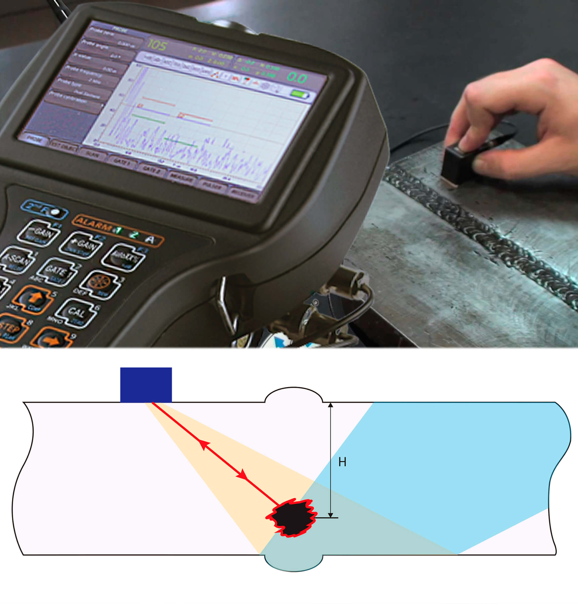
With the pulse echo technique, the transducer sends a probing signal to a test object and receives echo signals reflected from defects, as well as from design features of the product. Based on the time of the signal arrival, it is possible to spot the location of the defects, and based on the signal amplitude - the size of the defects. The disadvantage of this technique is the need for the defect to have a reflecting surface perpendicular to the ultrasonic beam, or be located near the surface of the product. For example, the pulse echo technique does not allow detecting planar defects (cracks and lack of fusion) that are not located close to the surface of the product under test.
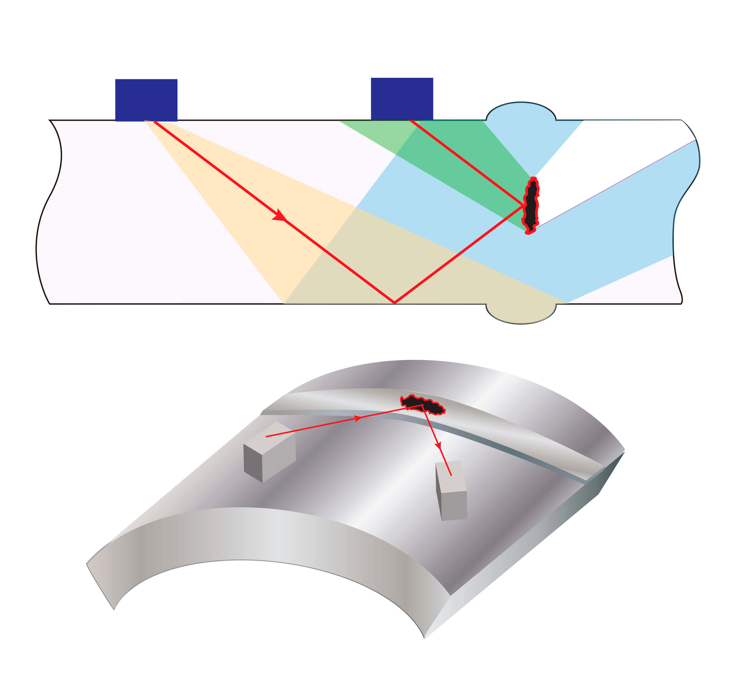
The pulse echo technique does not allow detecting planar defects (cracks and lack of fusion) that are not located close to the surface of the product under test. The pitch catch techniques, Duet and Tandem, are used to recognize the above mentioned flaws. This is achieved with a pair of transducers installed so that the signal emitted by the first transducer is returned to the second transducer after reflection from the planar defect.
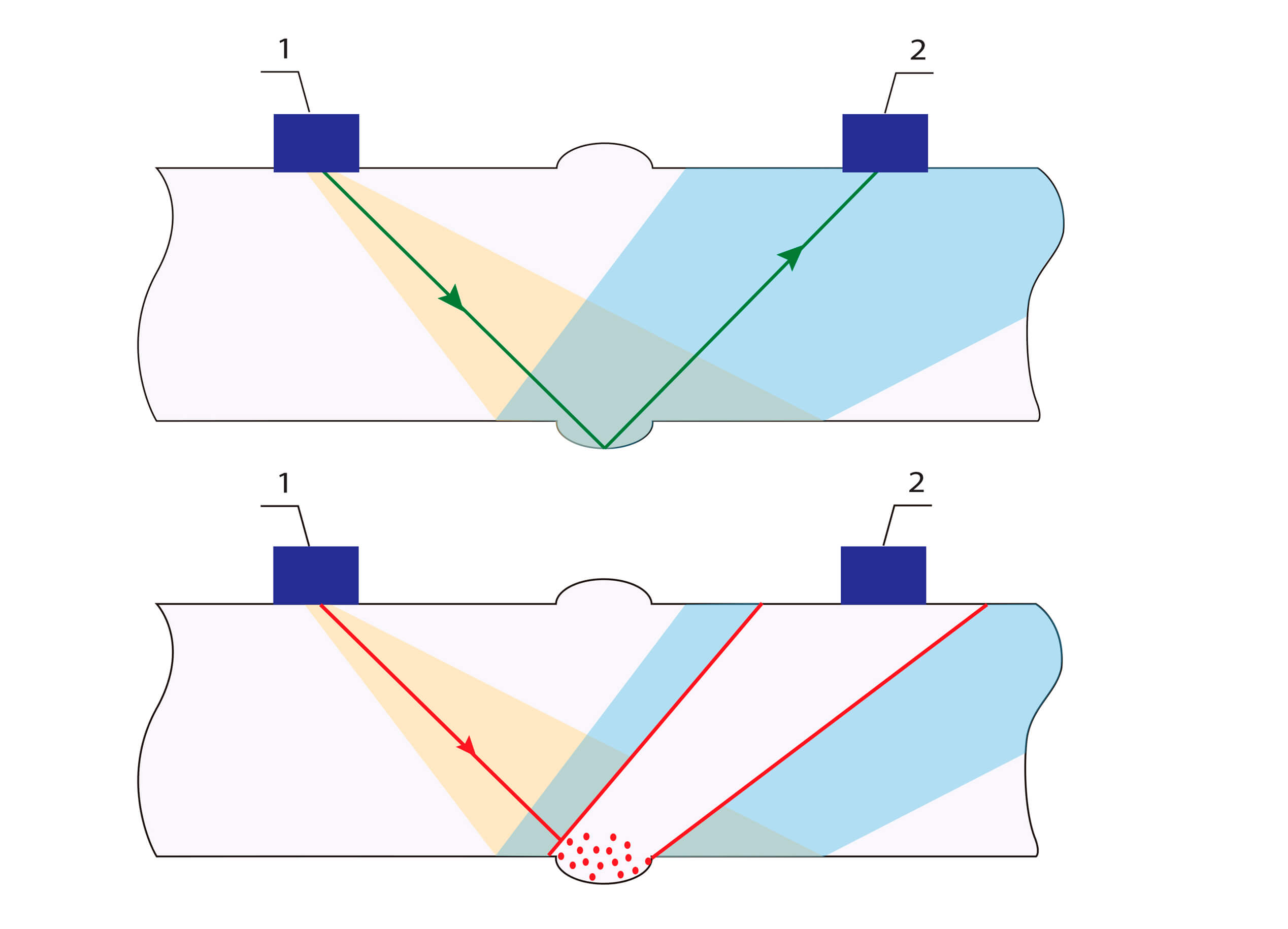
However, even the pitch catch mode does not guarantee the detection of all differently-directed flaws. For this purpose, the through transmission technique is used, with the transducers placed on both sides of the weld so that the signal reflected from the back surface comes to the receiver. Sufficiently large defects of almost any orientation crossing the ultrasonic beam shade the above signal, which evidences their detection. But, unfortunately, this technique does not provide exact information about the location (coordinates) of detected flaws. To obtain accurate readings from the ultrasonic flaw detector, it is necessary to make preliminary settings with the help of specialized reference blocks that are usually supplied together with the instrument. The reference blocks of various types can be also purchased separately, depending on a particular application or specific NDT task.
In recent decades, the ultrasonictime-of-flight-diffraction (TOFD) technique for weld examination has become increasingly widespread. The TOFD technique is based on interaction of ultrasonic waves with the edges of discontinuities. This interaction leads to generating diffraction waves with a wide range of angles. The detection of diffraction waves enables to establish the presence of discontinuity. The transmission time of reported signals is a measure of estimating the discontinuity height, thereby allowing to measure the discontinuity size which is always determined by the diffraction signal transmission time. The signal amplitude is not used for size measurement. Both longitudinal and shear waves are generated and applied in this case. The main information characteristic is the arrival time of the signal. The TOFD technique has a number of benefits as compared to conventional manual ultrasonic testing: Several-times higher productivity; Low sensitivity to the orientation of defects; Possibility not to estimate but measure the actual sizes of planar defects; High degree of reportability of test results. To implement the TOFD technique, special equipment is used with one or several pairs of transducers that are placed on both sides of the weld and moved along it during inspection.
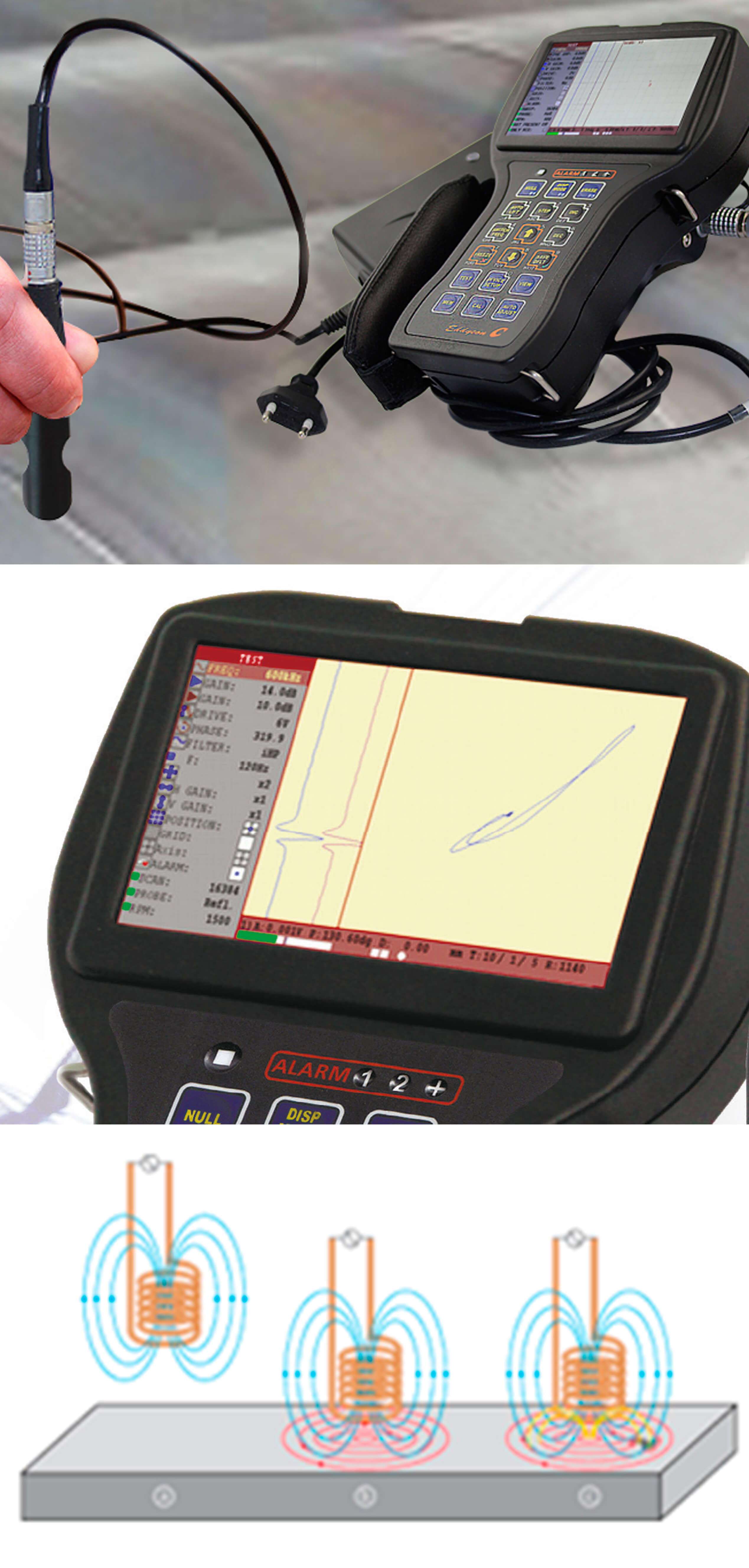
Eddy current non-destructive testing is based on the analysis of interaction of an external electromagnetic field with the electromagnetic field of eddy currents induced in a test object by this field. The operating principle of ET detectors is based on the eddy current method, which consists in the distortion of eddy currents in the local test zone, followed by recording the changes in the electromagnetic field of the eddy currents that are caused by the defect and the electrophysical properties of the test object. This method is characterized by small test depths, as it is used to detect cracks and discontinuities in the material at a depth up to 2 mm. The design and setup procedure of eddy current testers resemble the design and setup procedure of their ultrasonic counterparts, using eddy current probes and eddy current reference blocks accordingly. Obviously, the ultrasonic and eddy current testing methods complement each other, ensuring a hundred-percent reliable examination of the weld over its entire depth and extent. OKOndt GROUP manufactures a series of eddy current flaw detectors for non-destructive testing of welds.
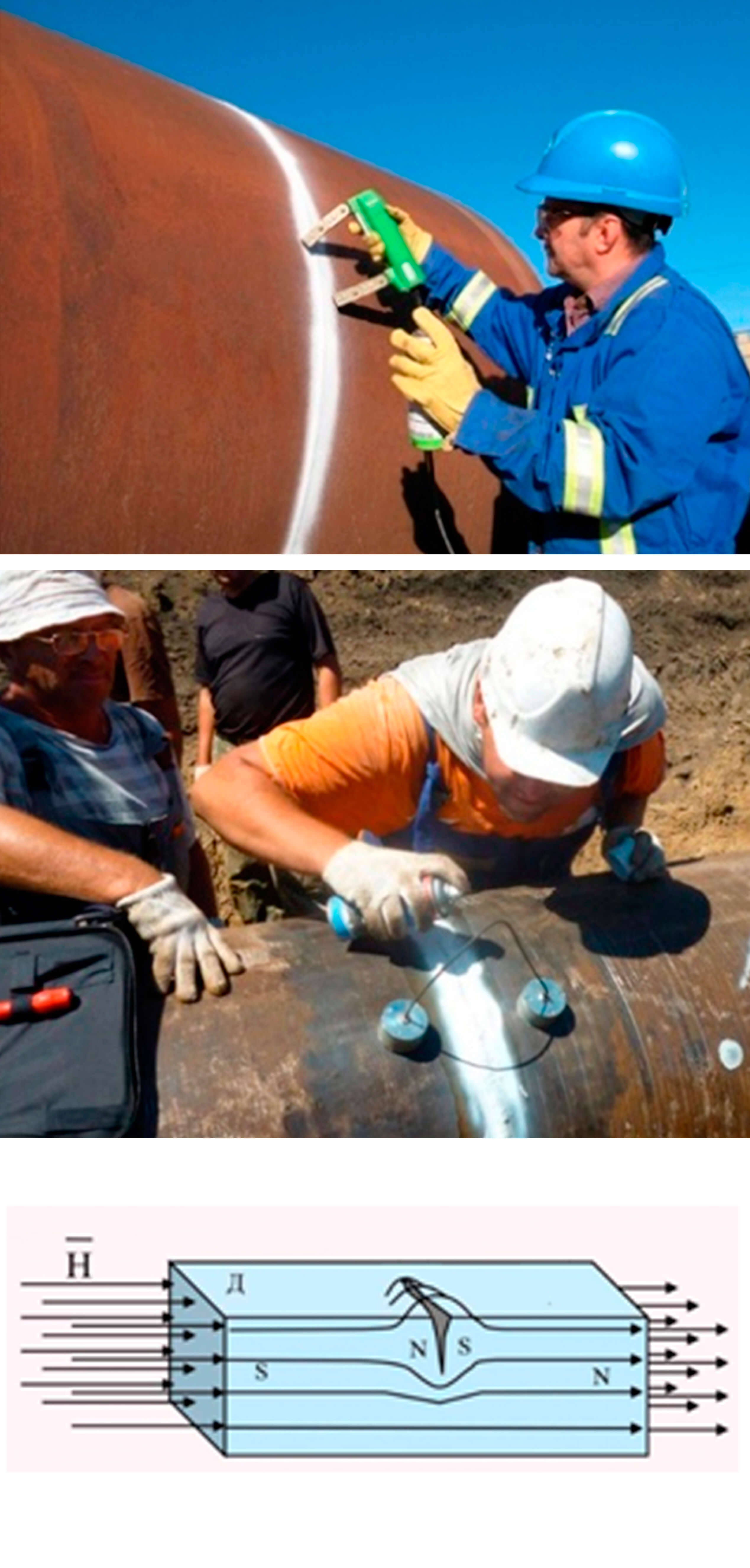
Magnetic particle inspection is a method of non-destructive testing based on the phenomenon of attraction of magnetic powder particles by magnetic scattering fluxes that arise over defects in magnetized control objects. The magnetic particle method is designed to detect surface and subsurface discontinuities such as hair, cracks of various origin, non-melting of welded joints, floken, sunsets, tears, etc. The Magnetic Particle Flaw Detector allows you to control various shapes, welds, internal surfaces of the holes by magnetizing individual controlled areas or the product as a whole with a circular or longitudinal field created by a set of magnetizing devices powered by pulsed or direct current or by using permanent magnets.
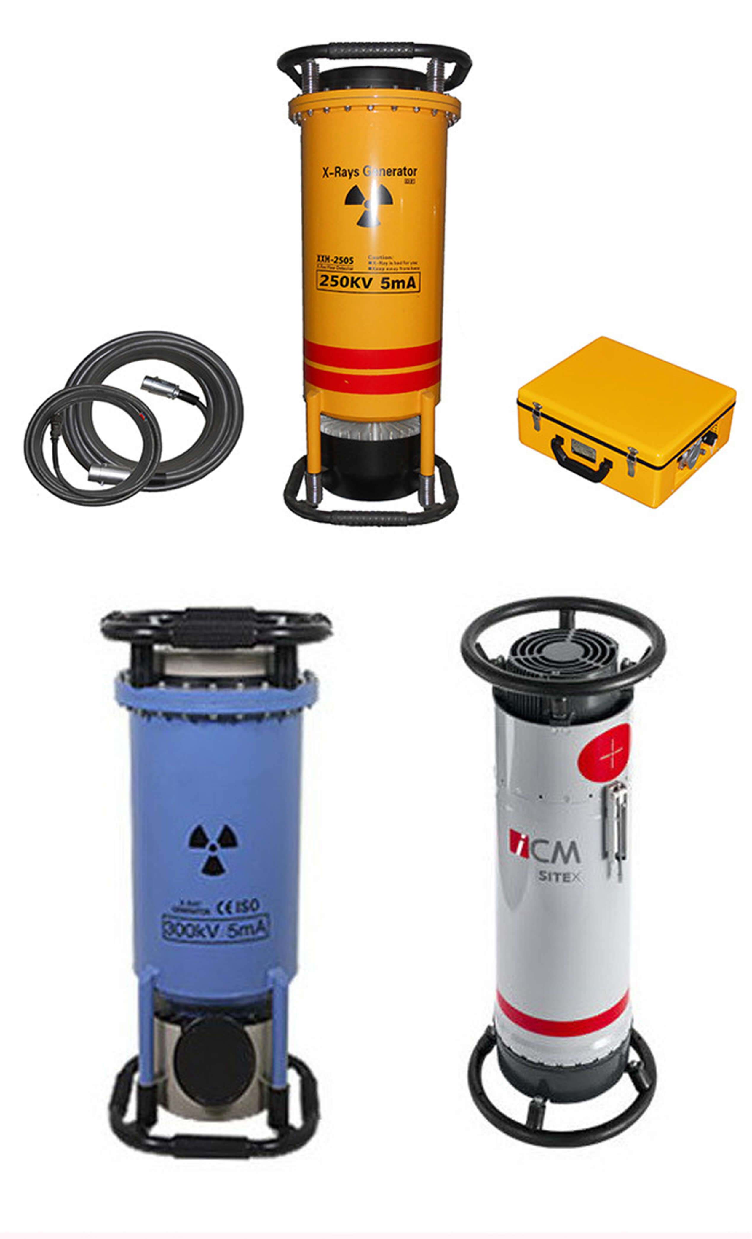
Radiography is described here only with the aim to provide a complete picture of NDT methods that are used for welds examination. Although this method is quite rigorous, its application is rather limited because it is associated with the use of gamma rays and X-rays with high permeation power, which allows them to pass through the metal, whilst the defects are recorded on the film. This increases danger to human health. In addition, instruments of this type are quite expensive. So, this is a very specific testing method that requires the use of appropriate personal protection equipment, as well as the creation of laboratory conditions for testing. Thus, we have considered the main methods of non-destructive testing of welds. It is obvious that the combined use of ultrasonic, eddy current and magnetic particle inspections ensures the most accurate test results and the safe test conditions.
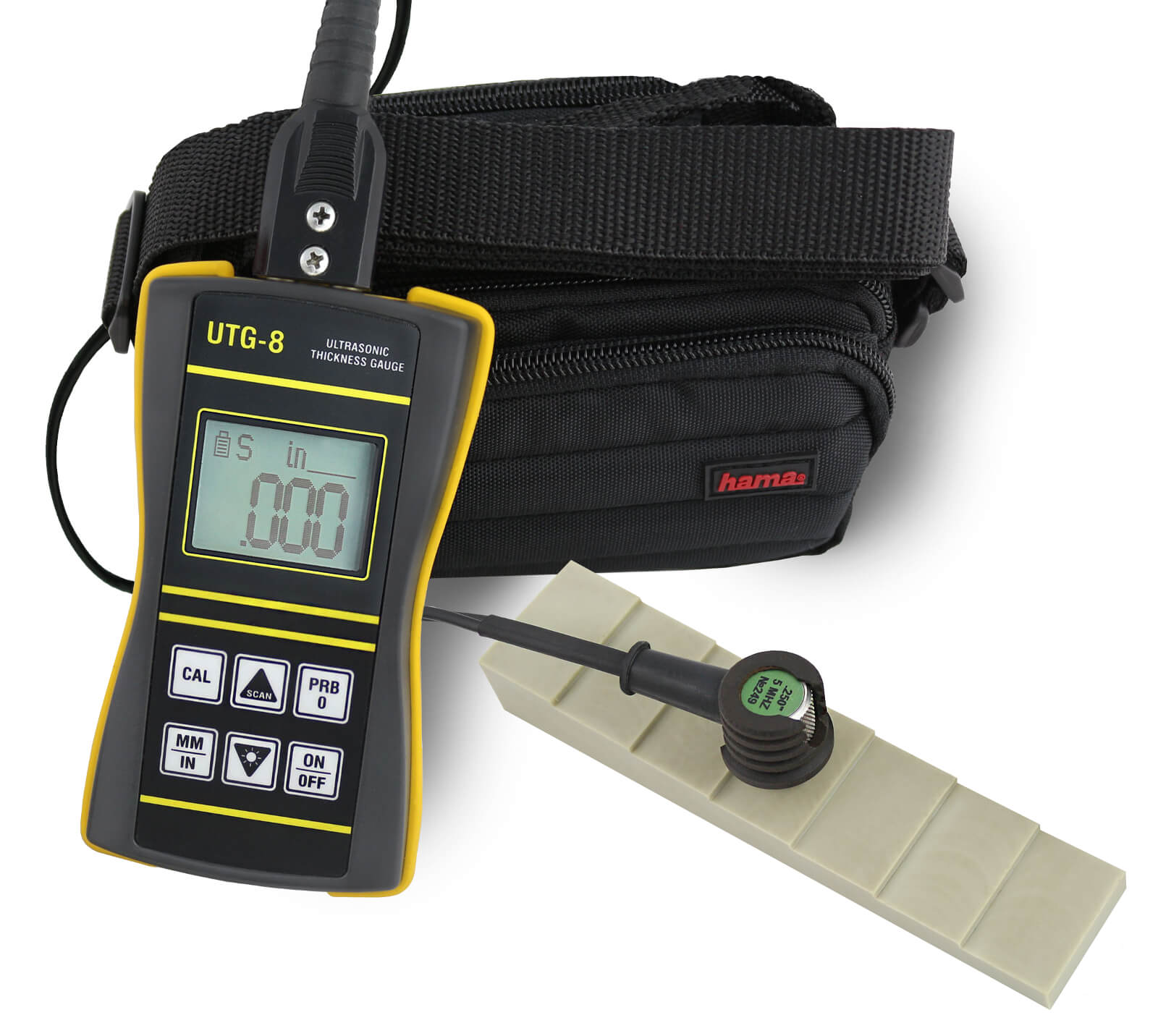
For easy tasks not requiring structural data storage or corrosion mapping, a simple, reliable and easy to use ultrasonic corrosion gauge UTG-8 is used.
The device operation is maximum simplified. You have to connect the transducer, to calibrate the device on the in-built calibration block – and you may start measurements. The device also supports one-point and two-point calibrations.
When taking measurements there is also a so-called gauging accuracy indicator displayed on the screen – the more it is filled, the more accurate measurements are.
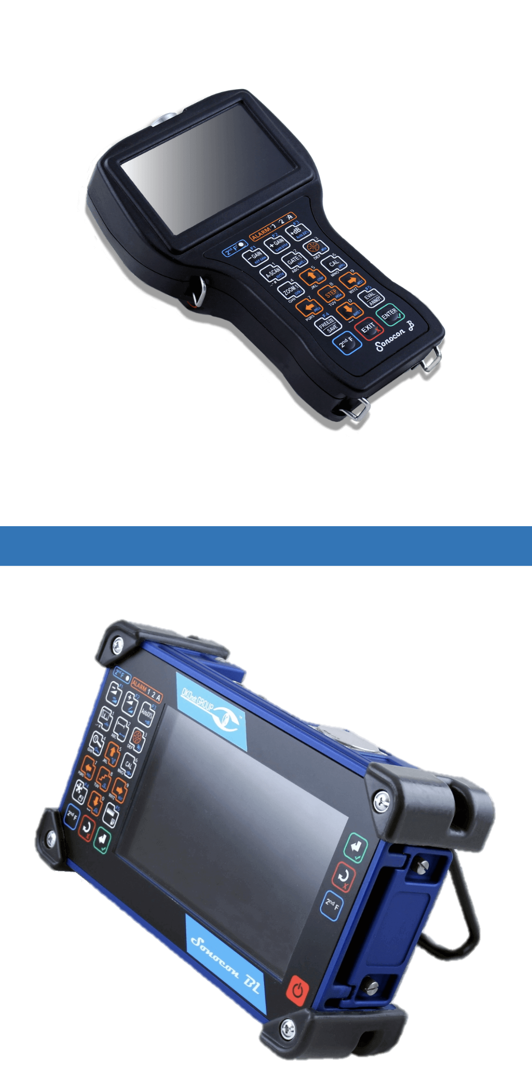
There is also a wide range of tasks, where it is required not only to measure the remaining thickness and search for corrosion damages, but also to analyze the whole measurements picture, their statistical analysis, measurements database and test reports formation. In order to solve these tasks, there are the Sonocon devices family made by OKOndt Group: Sonocon B and Sonocon BL. The devices have the same set of functions differing only by their form-factor. Sonocon B can be easily fit in your hand and weighs only 2 lb, though it is equipped with 800×480 pixels and 4.5 in display. Sonocon BL has 7.5 in diagonal screen with the same resolution, polyurethane-reinforced bumper case and extended keyboard. Meanwhile, its weight is only 3.5 lb.
Both devices have switchable software allowing to apply them as a universal flaw detectors («UT» version), and as the A-Scan ultrasonic corrosion gauges, and corrosion plotters («Thickness gauge +» version). With regards to the subject of the article, further we will speak about «Thickness gauge +» version functionality.
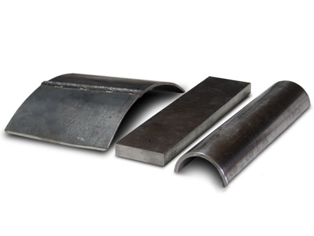
Both the manufacture defects – the ones that appear in the process of production – and in-service defects of fatigue type may develop (fig.1) in various metal products. The cracks may develop at different angles to the surface growing to considerable depths thus causing the threat of a product breaking when in service.
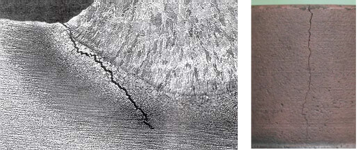
Figure 1. Cracks in metal products
The task of these defects detection can be resolved by a number of testing methods. For instance, magnetic particle, eddy current, ultrasonic and others.
The task of cracks depth evaluation is as important as defects detection is. Defects depth evaluation may be in demand in those industries where the repair of parts and products using the methods of mechanical treatment is required: turning, polishing, milling and others. Based on the value of a defect depth a decision about the utility of a part repairing can be taken, that in turn will allow to considerably decrease the costs if compared to the part replacement.
In comparison with the eddy current testing, magnetic particle method only allows to confirm whether there are cracks in the object. The eddy current testing method, additionally to the defects detection, enables to evaluate their depth.
Cracks depth can be also measured by the ultrasonic TOFD or delta method . However, their usage requires much effort and operator’s experience in comparison with the eddy current method. At the same time, the ultrasonic testing method allows to perform measuring the height of a crack not only on the scanning surface but also on the opposite side, and even of internal cracks. That is why for cases when there is no access to the surface from which a crack has started to develop, as well as for the internal cracks, it is recommended to use the ultrasonic method of testing; and to evaluate the depth of cracks developing from the test surface it is advisable to use the eddy current method.
To date, the task of evaluation of the crack-type defects is vital in such industries as
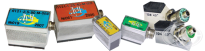
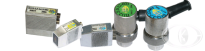
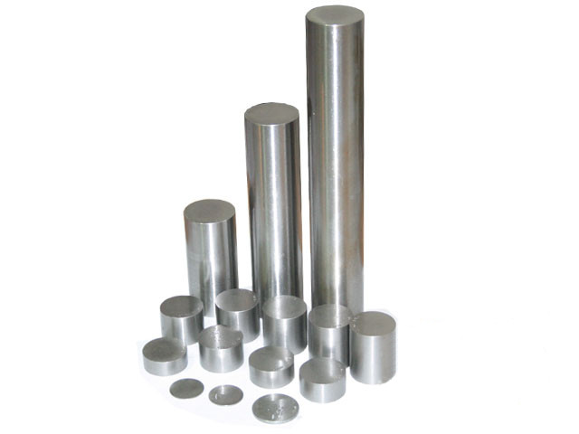
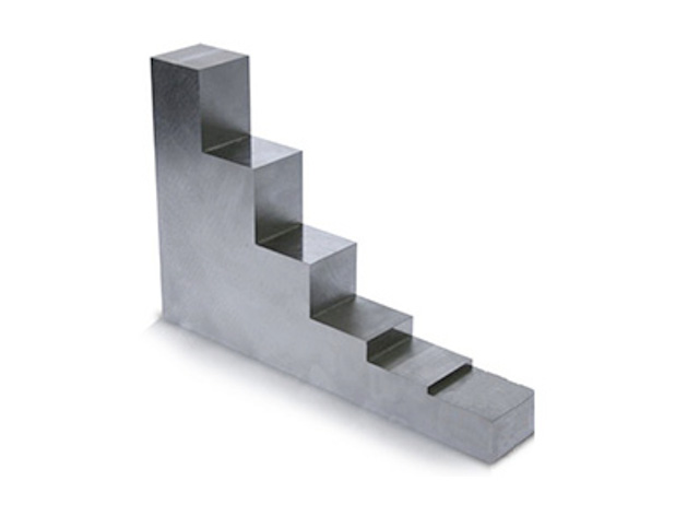
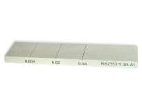
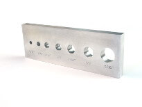
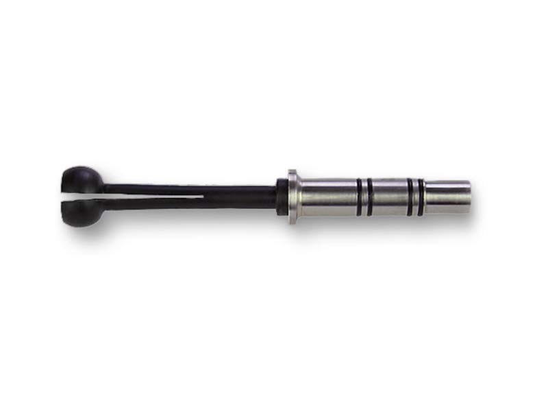
Taking into account the evident advantage of the eddy current method when dealing with crack depth evaluation and understanding the importance of this feature for industrial enterprises the developers of OKOndt implemented in their portable devices Eddycon C and Eddycon CL, as well as in some mechanized systems, the possibility to estimate defect depth, in millimeters. The correct operation of this feature requires a preliminary calibration using a calibration block. In typical cases either the flat block (fig. 2) or a flawless fragment of the test object with the artificial flaws on its surface may be used (fig. 3).
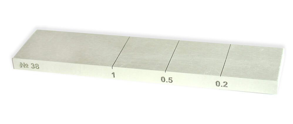
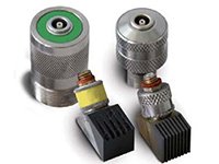
Figure 2. Calibration Block RS2353/1-3N-Fe
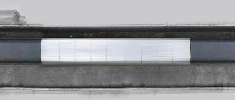
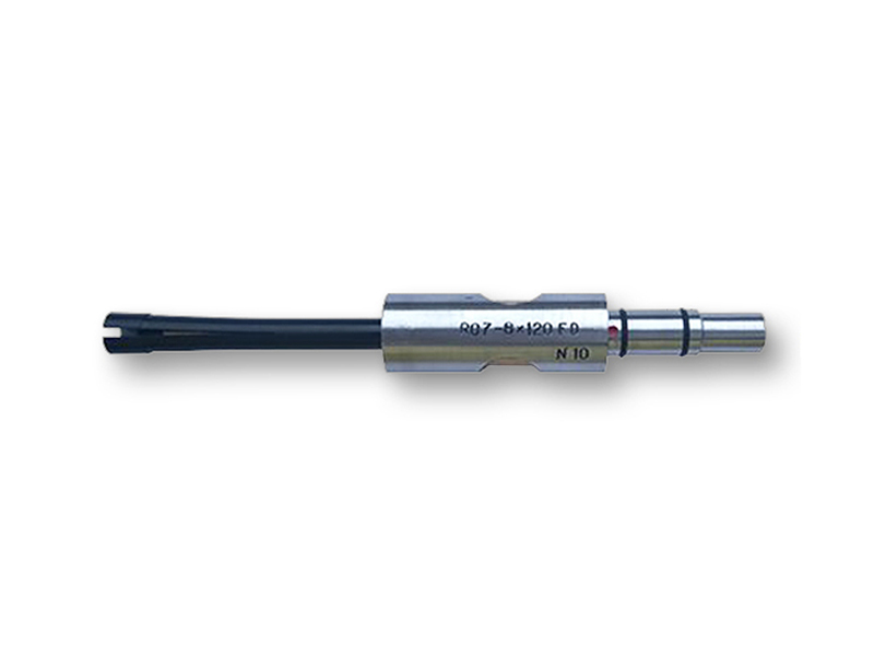
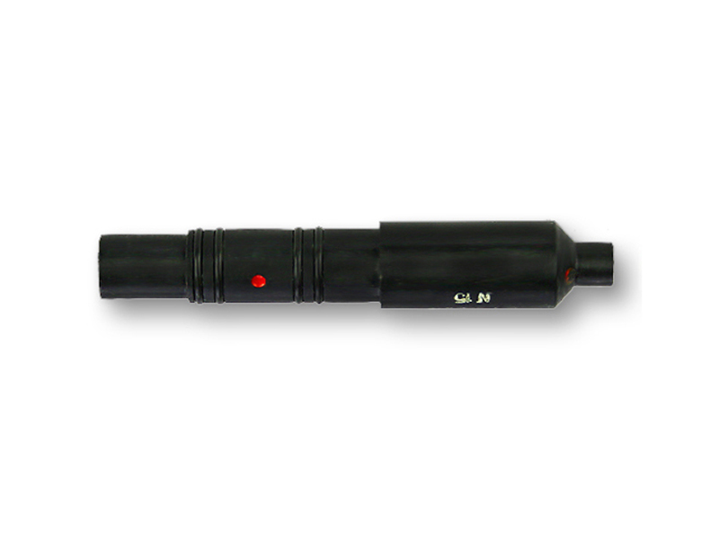
Figure 3. Calibration Block for Mechanized Rail Eddy Current Flaw Detector ETS2-77
After having performed a few simple calibration procedures, the device will calculate the depth of the surface defects in millimeters in accordance with the calibration curve that has been already built (Figure 4).
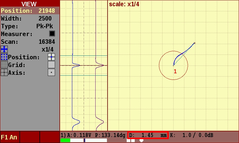
Figure 4. Flaw detector’s readings at the defect crossing on the test object
Therefore, the decision about the repair or replacement of a part is taken.
Cracks depth evaluation allows to optimize the repair and replacement processes of the industrial equipment without compromising the safety of its operation.
Using eddy current devices with the crack depth evaluation feature enables the enterprises to get a considerable economic feasibility due to a more effective inspecting of their equipment and cutting service-related expenditures. As for the railroad transport, piping and power industries – knowing the exact data about the depth of a detected crack allows to timely take the required measures thus preventing serious problems, and even disaster, that may be caused by the damaged object.
Ultrasonic method occupies a
special place in non-destructive testing. Being one of the first and the
most widespread it allows to detect both surface and inner defects of
various types, perform thickness gauging and non-destructive
structuroscopy.
_1760443585.webp)
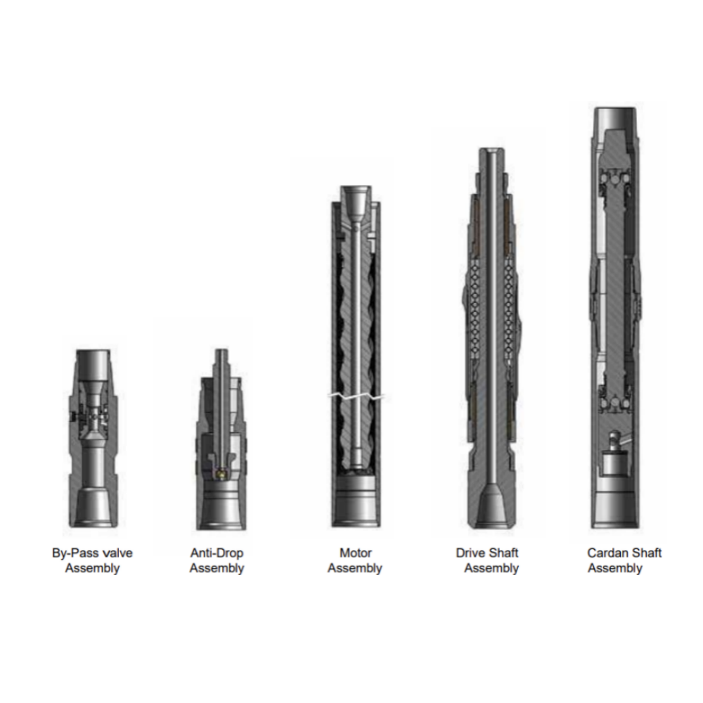
Downhole motor is a kind of downhole dynamic drilling tool driven by the power of drilling mud. Mud stream from the outlet of a mud pump flows through a by-pass valve into the motor. This stream produces pressure loss at both inlet and outlet of the pump, to push the rotor into rotating, and to transmit the torque and speed onto the bit. The downhole motor property mainly depends on its property parameters.
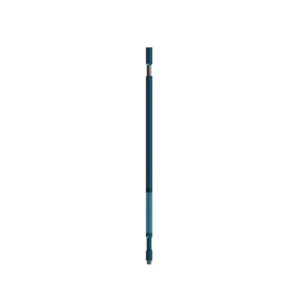
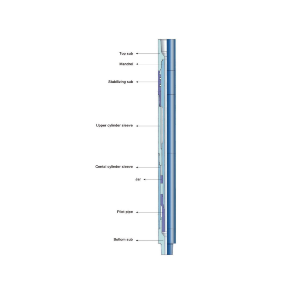
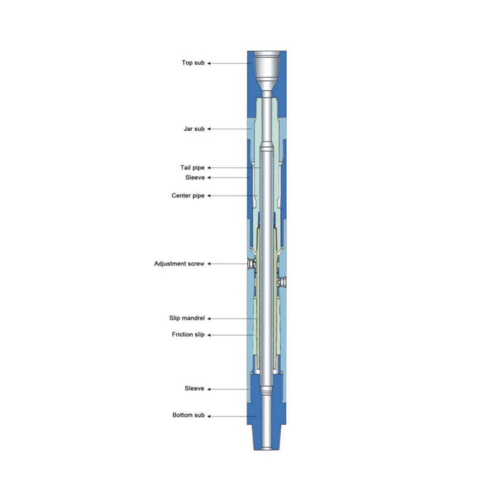
QY type high temperature hydraulic drilling jar is a new generation of double-acting hydraulic jar that is fully upgraded by our company on the basis of the original QY full-hydraulic drilling jar. It has the characteristics of simple operation, adjustable shock tonnage, high temperature resistance, etc. This type of drilling jar adopts a new hydraulic delay release system, which has excellent reliability and wide adaptability.
Application It is suitable for all conventional wells, inclined wells and large displacement wells at all temperatures not higher than 204℃.
Features
The superior machine structure is to further improve the machine maintainability. The unique sealing structure is designed to improve the temperature resistance and improve the sealing reliability. The core mechanism adopts the seal oil bath design to reduce the wear and tear of the moving parts and improve the life of the whole machine.
The overflow area of the release channel is increased to reduce the running resistance and greatly improve the shock effect.
The operating force of hydraulic releasing mechanism can be controlled on the ground by driller, and can be flexibly adjusted according to the downhole situation.
The optional mechanical locking module is added to meet the needs of some special users.
The optional mechanical locking module is added to meet the needs of some special users.
Increase the fast recovery function of the upward and downward strokes. The mandrel moves back to the middle position, and then the jar will do jarring again in either of the two directions.
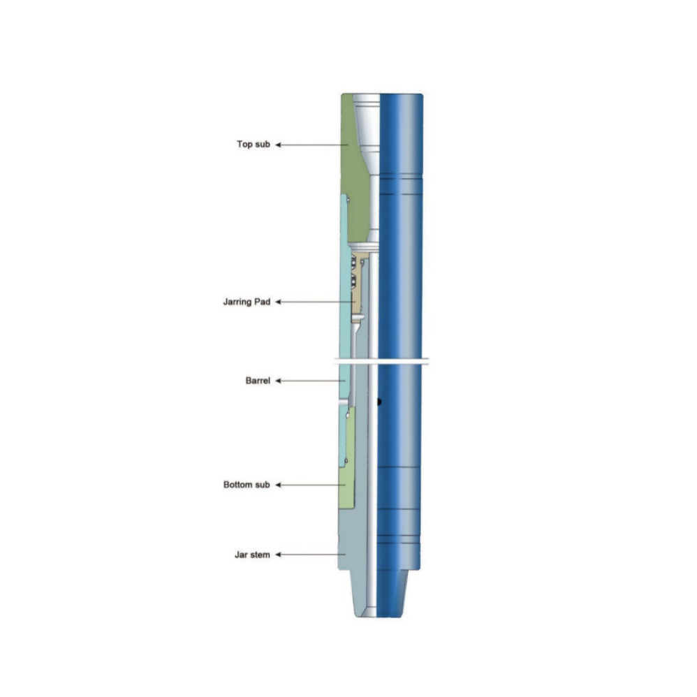
QY type hydraulic drilling jar is a new generation of double-acting hydraulic jar that is fully upgraded by our company on the basis of the original QYSZ Ⅱ type full-hydraulic drilling jar. It has the characteristics of simple operation, adjustable shock tonnage, high temperature resistance, etc. This type of drilling jar adopts a new hydraulic delay release system, which has excellent reliability and wide adaptability.
Application
It is suitable for all conventional wells, inclined wells and large displacement wells at all temperatures not higher than 160℃ .
Features
The superior machine structure is to further improve the machine maintainability.
The better sealing materials are selected to improve the reliability of sealing
The core mechanism adopts the seal oil bath design to reduce the wear and tear of the moving parts and improve the life of the whole machine.
The overflow area of the release channel is increased to reduce the running resistance and greatly improve the shock effect.
The operating force of hydraulic releasing mechanism can be controlled on the ground by driller, and can be flexibly adjusted according to the downhole situation.
The optional mechanical locking module is added to meet the needs of some special users. Increase the fast recovery function of the upward and downward strokes.
The mandrel moves back to the middle position, and then the jar will do jarring again in either of the two directions.
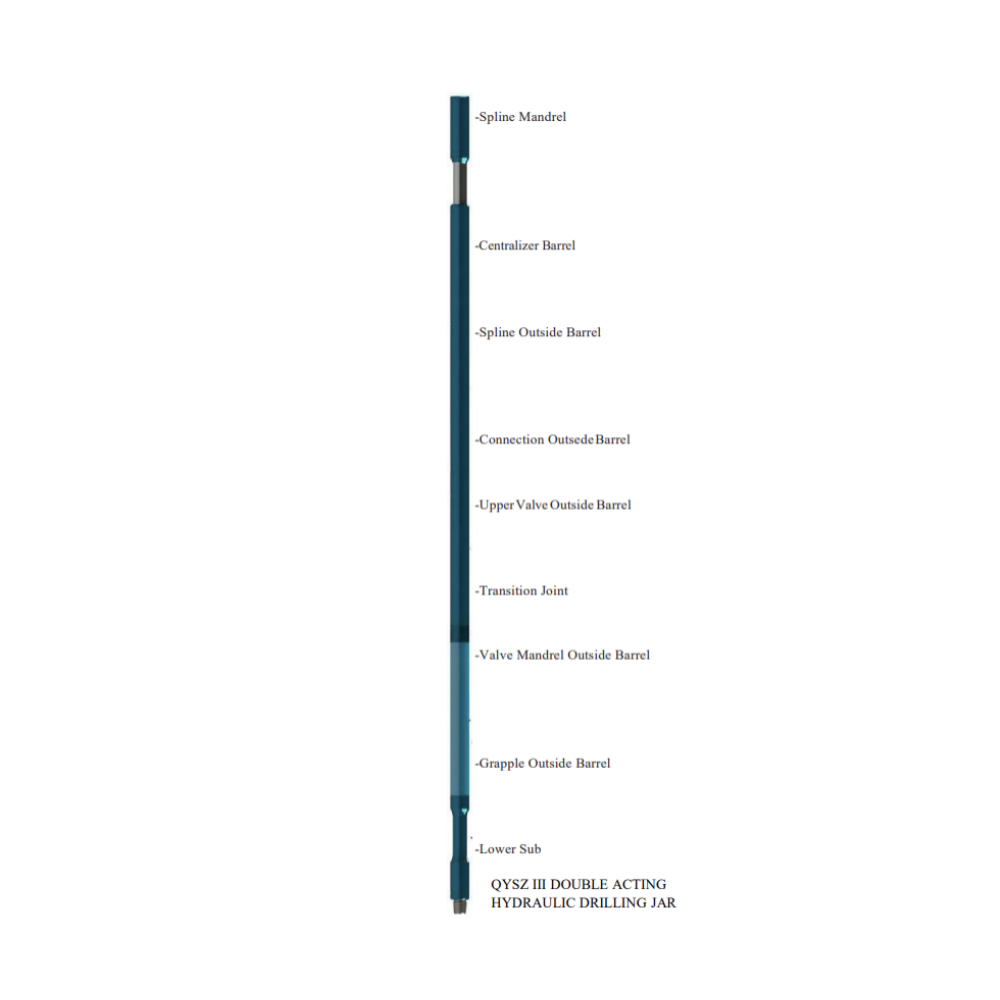
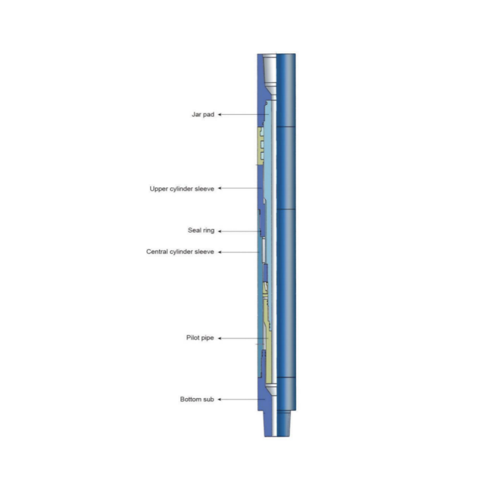
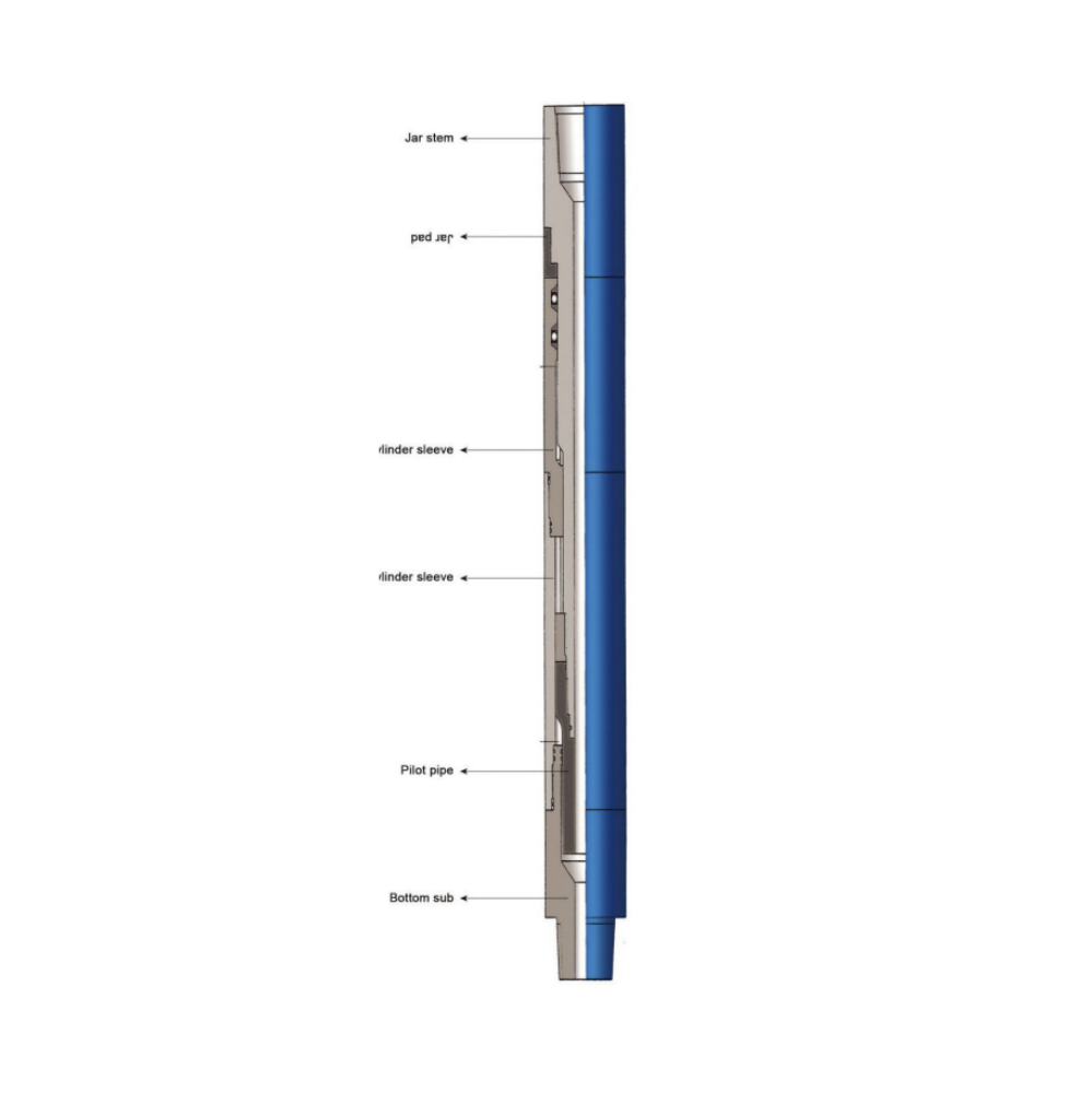
QYSZIII New Double Acting Hydraulic Drilling Jar is a new hydraulic drilling jar with locking mechanism developed on the basis of the structure of QYSZII double-acting hydraulic drilling jar. Besides the advantages of QYSZII type, it also has the following advantages.
1.The mechanical locking mechanism prevents unnecessary wear of the internal parts during the working process, and improves the working life.
2.The mechanical locking mechanism is functional safety and reliability, which is made by special process. The friction resistance is small, and the locking force is linear stability.
3.The locking mechanism can avoid the failure jarring caused by mis operation when connect simple root to the drill string or contact the hole bottom.
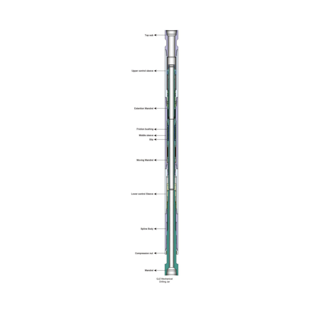
QJZ type mechanical drilling jar is a kind of fully-mechanical jarring tools. It can release the drilling tools sticking accidents by providing a up and down jarring force. Basically, it is part of the drill stem, whenever needed, the jarring force can increase the working efficiency.
The drilling jar is consists of drilling up jar and drilling down jar in one body, which has stable working performance and strong jarring force both up and down. When in down hole, it can release the struck; it is a desire tool for directional well and deep well.
Working Principle
Up Jarring
Lowering drill string to make drilling jar closed completely (in locking position), elevating drill string by the order of small tonnage to larger tonnage, which make spring and hydraulic cylinder delay, when mandrel move to a position and become release resistance, the spring force stored in drill string will transfer to up forward energy and up jarring. Repeating the above several times can force tool to produce continues up jarring.
Down Jarring
Move up and down the drill string to make drilling jar closed completely (in locking position), lowering drill string to make spring compressed and stored energy. When pressure of jar is larger than the desired lower unlocking force, grapple will slide out from mandrel to release the locking and make down jarring. Repeating the above several times can force tool to produce continues down jarring.
The drilling jar connecting with drill tool and working with drill strings is a downhole stuck freeing tool in drilling operation. When drill tool is happened to be stuck in downhole, the stuck drill tool can be released by in time starting the drilling jar to provide continuous up jarring or down jarring. It is a desire tool for directional well, complicated well and deep well. The drilling jar is consisting of ZSJ type drilling up jar and ZXJ type drilling down jar, both can be used mutually or operated separately. The up jarring section takes use of hydraulic mechanism; the jarring force can be adjusted according to up elevating load but can not exceed the max. load for tool load rated. The down jarring section takes use of mechanical friction mechanism; the jarring force is well preadjusted by adjusting device before put into down-hole. No re-adjustment can be allowed after jar is put into down-hole.
The SJ type two ways shock absorbers are used to simultaneously slow down or eliminate the vertical or horizontal shock from drill string. It can reduce the damage due to shocking to drill bit, drilling tool and surface drilling tool so as to enhance drilling speed and reduce drilling cost.
Working Principle
The torsion of bottom hole will be changed with changes in bit structure, formation and bit weight. When the drilling speed reaches up to a certain value, torque and resonance will be happened to drill string. During rotation drilling, the lower part of drilling tool simultaneously bear axially pressure and torque. When bit weight exceed the limit value, the drilling tool will produce a transverse bending (it means lose steadiness) and torque can also make the drilling tool to lose steadiness to be turned into a twist shape.
Two positions are very typical:
1. The lower bit is suddenly frozen and then torque bumping will be produced unless the cut down rotary energy.
2. Reversing operation in force.
The vertically damping unit is made of mandrel, piston assembly, annular space damping unit and liquid spring of working chamber. Working mechanism: To absorb or release the vibration energy of bit and drill string by means of compressible liquid producing spring deformation in working chamber under the function of pressure. The mandrel moves axially relative to outer barrel when liquid spring is in compression or explanation. Meanwhile, the non-compressible liquid in damping chamber flows through damping space and produces a large number of friction heat so that some vibration and bumping energy are used up. The vertical bumping unit thus can absorb or reduce the drilling tools’ energy in vertical vibration and bumping.
The piston change-over unit is composed of spline outer barrel which is connected with piston by rectangular spline pair and the piston inner hole which is connected with mandrel by ladder-shaped spiral pair. Such a group unit can turn the torque vibration and impact load into vertical component of force in working chamber in a twinkling of an eye so that a constant torque is maintained on.
The YJ type one-way shock absorber (bumper )is a kind of drilling tool. It can effect shock absorbing and shock reduction by means of elastic deforming and anti-coagulation produced from hydraulic oil under the outside force. Its advantages such as simple structure, reliable working performance and easy to maintain can well absorb shocking and vibrating load from drill strings during drilling operation. Therefore, using of shock absorber can raise in structure the service life of drill bit and drill pipe, speed up drilling, get rid of drilling jumping, well protect surface equipment's and drilling tools.
Working Principle
The hydraulic shock absorber is connected between drill bit and drill collar, the torque is transferred from top drill string to mandrel. The spline transfers torque to spline outer barrel, oil cylinder and lower sub, then drive drill bit to rotate.
The bit weight is from the which of top drill tool so that drill bit insert drill into formation to break rock into pieces. The drilling mud is fed through bore of drill pipe and drill collar into mandrel of shock absorber, tailpipe, lower sub bore and ejected into bottom well .Because of the uneven bottom well conditions and special structure of cone bit, the drill bit and drill string during drilling operation would produce severe vibration. The hydraulic shock absorber, by means of compressible deformation of compressed liquid under the function of pressure, absorb the energy from drill bit and drill string vibration. Thus, the shock absorber can reduce the vibration and impact load of drill tools.
CSJ type super fishing jar is a fishing tool which the jarring force is larger than other jar with same specifications. It features a closed structure, reliable performance, easy to adjust and easy to operate. It is a new type of top jarring tool used in oilfield, geological exploration and drilling operation.
Working Principle
CSJ type super fishing jar effects the top jarring action is by means of hydraulic mechanism which allows taper piston to move in cylinder and stores energy by raising drill tool. When the drill tool attached on the top of super fishing jar is raised, enough time is provided for drill tool to store energy due to the damping action between taper piston and sealing body in pressure body of super fishing jar. When taper piston moves to release bore, the drill tool shall suddenly attract and produce an upward dynamic load along with the instant unloading of high hydraulic oil. The reliable impact working face is designed in the product structure to ensure that large jarring force is provided to stuck fish (drill tool ). A desire return mechanism is designed in order to make a reciprocating jarring action. In order to make a rotation for drill tool in down hole and a circulation for fluid, CSJ type of super fishing jar pass torque by means of spline and meanwhile enlarge the watercourse as far as possible to meet the tests with exception of fluid circulation and other applications.
The ZJS type jar intensifier is a kind of down hole fishing jar designed to increase jarring energy to top jar. Therefore, it must be run in conjunction with YSJ type hydraulic top jar or CSJ type super jar. Its main function is to supply acceleration to the upper end of the jar during the free jarring stroke. With a special function, the intensifier is essentially a fluid spring which not only can accelerate the top jarring action but also make the jarring action directly to strike on the fish and reduce damages to the drill tool and fishing tool.
Working Principle
When it is used, the jar intensifier is connected on the top of drill collar and on the lower end of drill stem. When the fishing tool engage the fish and the drill tool is lifted up, the silicone oil in the top chamber of piston is compressed and a large number of energy is thus stored. During lifting, when top jar reach up to free impact stroke, the stored energy in the jar intensifier will suddenly release, the energy suddenly released will provide a very large acceleration for drill collar and top jar to move upward. When the top jar reaches up to max. Stroke, a strong top jarring action will impact directly on the fish, as a result, one time jarring is produced, and more times jarring will be effected by repeating this course.
KXJ type bumper jar (hereinafter called as bumper jar )is a mechanical jarring tool. It can make jar repeatedly the stuck drill stem to free from stuck point. When stuck drill stem can not be released by lifting and jarring, the bumper jar can be rotated to make releasable fishing tool to release fish. When used with mechanical internal cutter, it can provide an expected feeding force to the internal cutter so as to cutting steadily. When used with reversing unit, it can compensate the rising stroke for threads after reversing.
Energy conversion in jarring operation
Jarring downward is made by means of energy conversion. Raising drill stem shall make bumper jar to be pull down at a certain height to produce potential energy. Go on raising drill stem, the drill stem has a strain energy due to spring strain. When drill stem is lowered suddenly, the energy stored in drill stem force the drill stem to move downward in acceleration. When bumper jar reach a closed position, the above two energies at this instant change into large downward jarring force.
Main factors having influence on jarring force
The bigger hanging weight on top drill stem of bumper jar makes a bigger jarring force; The longer the spring extension of drill stem is when raising drill stem, the bigger the jarring force is; The longer the stroke of the bumper jar is, the bigger the jarring force of jar is.
YSJ type hydraulic up jar is used to be free from drilling sticking, through hydraulic principle, by means of elastic potential produced from drill tool elastic deformation. Once the elastic potential energy is released, it would produce a large up striking load to reach a purpose of fishing and coring. It features easy structures, strong jarring force, easy to return, convenient operation. If it is used with ZJS type jar intensifier, it may gain better jarring effect.
Working Principle
The key principle is: the piston moves up and make hydraulic so that it makes enough time to make drill tool to save energy. With the piston continue to move slowly to releasing bore, after the binding of hydraulic oil is released, elastic potential is released by drill tool saved, immense dynamic loading is passed to drill tool due to jar pad’s hitting on the bottom of up jar cylinder liner. A desire return mechanism makes are cipro catting jarring action.
Lubricated fishing bumper sub is one of the jars which produce jarring force by means of the energy caused by heavy weight objects when moving down, its inner chamber is full of hydraulic oil so as to ensure a longer service life. The tool is suitable for deep hole and middle deep hole operation. With some advantages: Can produce strong one way down jarring force, maximum jarring force, continuous down jarring force. Medium jarring force; continuous up jar, low-grade jarring force; can release fishing tool; can act as constant pressure drill tool, simply structure, easy operation, all these make it widely used jarring tool.
Working Principle
Energy conversion in jarring operation
Downward is made by means of conversion. Raising drill stem shall make bumper jar to be pulled down at a certain height to produce potential energy. Go on raising drill stem, the drill stem has a strain energy due to spring strain. When drill stem is lowered suddenly, the energy stored in drill stem the force the drill stem to move downward in acceleration. When bumper sub reaches a closed position, the above energies at this instant change into a large downward jarring force.
Main factors having influenced on jarring force.
Many factors influence on jarring force, but key factors as follows:
1、The bigger hanging weight on top drill stem of bumper jar makes a bigger jarring force.
2、The longer the spring extension of drill stem is when raising drill stem, the bigger the jarring force is.
3、The longer the stroke of the bumper jar is, the bigger the jarring force of jar is.
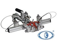
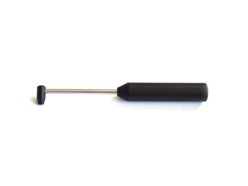
The surface jar is an effective tool for resolving the problem of drill tool stuck in down hole. It is connected with the surface section of drill string, the device to adjust the tonnage shall protrude from the rotary disc face, the violent down jarring to the stuck catch can be clearly seen when the surface jar makes jarring operation. The jarring strength for the tool can be easily adjusted and it is an easy operated, unique designed tool which can make continuous down jarring. The surface jar, which not only can bear heavy load and strong torque but also owns a good sealing property and can withstand the mud circulation with high pump pressure, has proven to be a safe, successfully effective releasing tool through many years using.
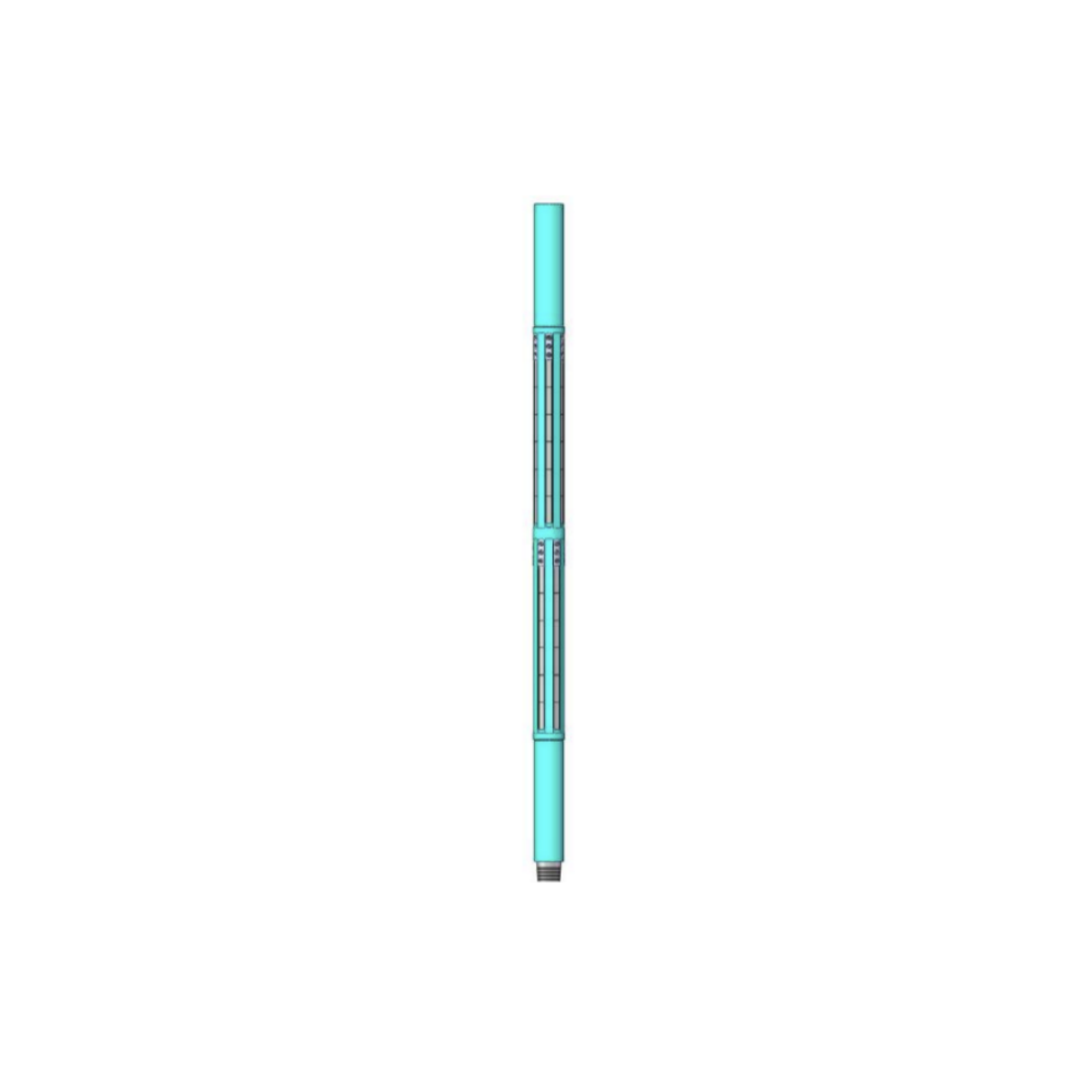
The agitator can improve the effectiveness of bit weight transfer and reduce the friction between drilling tool and borehole through the longitudinal vibration produced by the hydraulic action of drilling fluid, especially in the process of directional drilling to improve the bit weight transfer and reduce torsional vibration. It is a downhole tool used to solve downhole depressurization and improve weight on bit transfer. Smooth weight on bit transfer improves the ability to adjust the bit tool face to reach further target zones. It does not require too much work to adjust the tool face during drilling, keeping the tool face stable and increasing ROP. Particularly suited for horizontal, extended-reach Wells, it can be used in conjunction with MWD, screw, and any bit.
1. The Agitator can effectively reduce the friction between the BHA and the borehole wall and effectively improve the bit weight transfer in sliding drilling.
2. Reduces downhole torsion, reduces lateral vibration and increases ROP.
3. Directional drilling efficiency can be greatly improved, allowing for smoother boreholes.
4. Agitators can be used in vertical Wells, motor guided drilling, rotary guided drilling, extended reach Wells, shale gas reservoir drilling.
5. Can solve the problems of support pressure, slip and poor control of the bit on the tool face. Improve directional drilling tool face control, effectively improve the directional ability.
6. The pressure pulse generated by the hydraulic oscillator does not interfere with the MWD signal and will not damage the MWD instrument.
7. The Agitator has good adaptability to conventional PDC bit and roller cone bit.
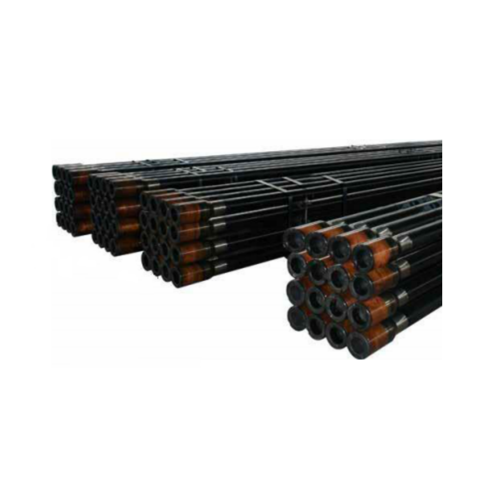
The common drill pipe is a rod that connects the drill bit, delivers the drilling fluid and transmits the power in the drilling tool. Our common drill pipe conforms to SY/T5561 and API Spec5DP standards. In order to reduce the wear of the casing and drill pipe, we can weld the wear belt at the end of the drill pipe female buckle joint. Our company has obtained the production and use license of ARNCO 100XT, ARNCO 150XT, ARNCO 300XT and ARNCO 350XT authorized by the American Anke company.
Product features
1. Mechanical properties and design of drill pipe joint, pipe body and welding area comply with API SPEC 5DP and RP 7G latest standards;
2. The end of the female buckle joint can be welded with a wear belt;
3. Both ends of the thread for phosphating treatment, with wire guard;
4. Both ends of the thread root can be cold rolling processing;
5. Both ends of the thread can be used for upper shackle test.
Ordering instructions
1. Select the required specifications, buckle type and quality code according to the specific requirements of customers, and indicate that the shoulder form of lifting platform is 18° or 90°;
2. Need to apply welding wear belt products, must indicate the use of welding wire brand, and indicate raised or flush type;
3. Need to do inner coating anti-corrosion treatment, must indicate the use of inner coating brand;
4. Special orders that do not meet the specifications and technical parameters in API Spec5DP shall be marked with special technical parameters, and the detailed dimensions of finished products shall be confirmed according to the corresponding sketches;
5. Whether there is a thread cold rolling or thread shackle requirements.
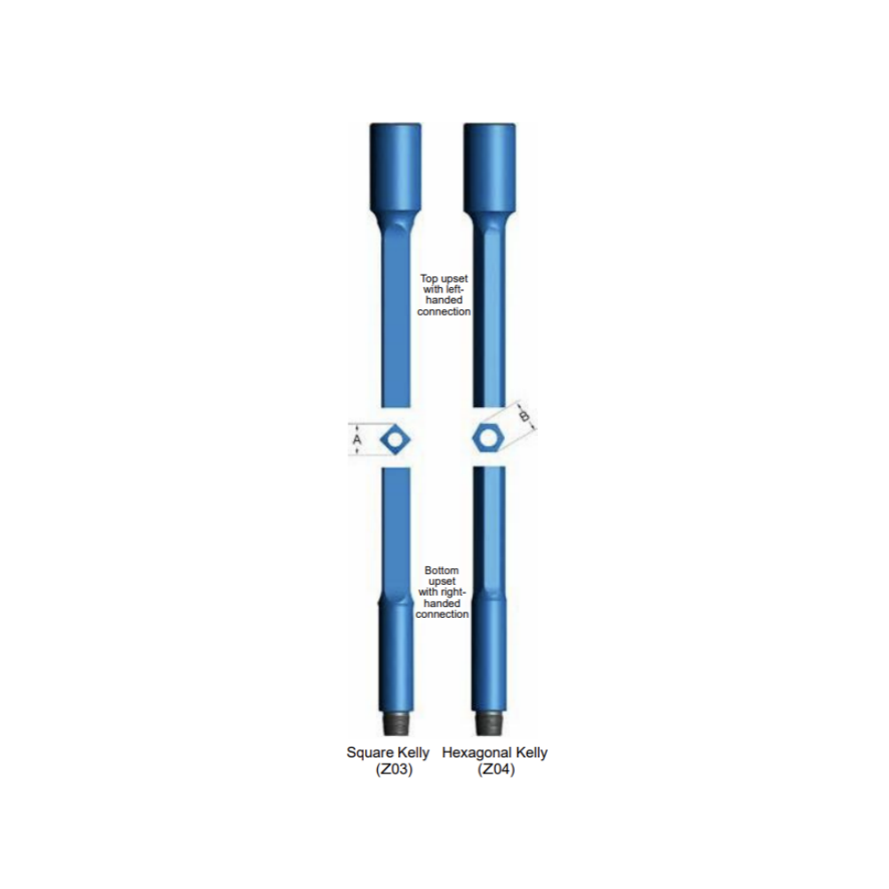
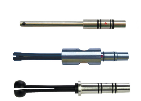
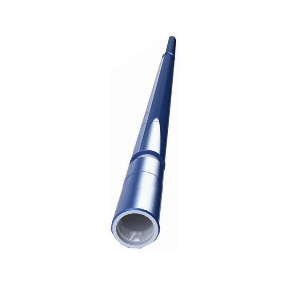
Kelly is main driver of the whole drill string. It transmits torsional energy from the rotary table through the drill string to the bit at the bottom of the hole. Kelly is a long square or hexagonal, precision machined heavy steel bar that is supported by the swivel through the rotary table and is connected to the first joint of drill pipe in the drill string.
Straightness of the Kelly is very crucial in the manufacturing process, thus straightness inspections are carried out before, during and after each machining operation. The flats are precision-milled to API specifications. All milling processes are performed on specially designed rigid Kelly mills to ensure tight tolerances and high quality drive sections. Each Kelly is furnished with a pressed steel thread protectors.
Describe
Features and Benefits
● Manufactured from AISI 4145H-modified, fully heat-treated alloy steel with a Brinell hardness range of 285-341BHn and a minimum average Charpy impact value of 40 ft-lbs.;
● Ends and drive sections, IDs and connections machined and inspected to API specifications;
● Ultrasonic inspection is performed on all sections;
● Shipped in a protective steel-cased scabbard;
When ordering please specify:
● Kelly type (square or hexagonal);
● nominal size and overall length;
● Upper and lower connections.
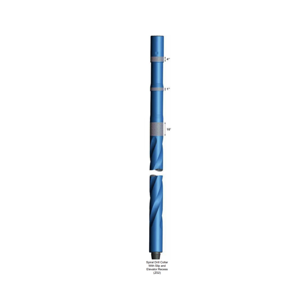
Spiral Grooving In order to reduce differential pressure sticking, the surface of drill collars can be spiral-grooved. Note 1-Loss of weight is approximatively 4%, compared to slick drill collars. note 2-Length of spiraled section allows reconditioning of connections.
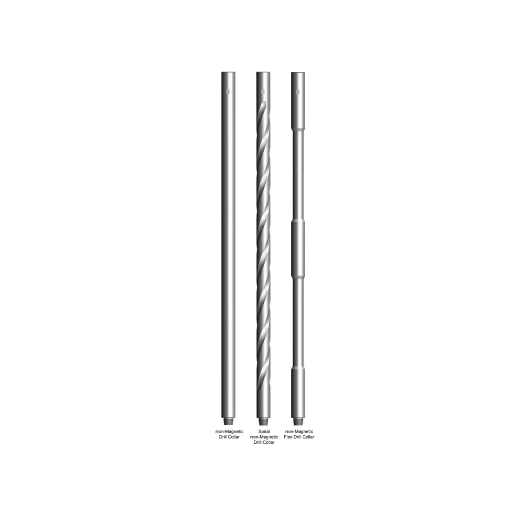
Non-magnetic drill collars are made from non-magnetic steel bars with low-strength by combining a proper chemical analysis and rotary hammer forging process with low magnetic permeability and excellent machinability. It will not interfere with the specialized directional equipment but rather will enhance the performance of the drilling operation.
The non-magnetic drill collars function as a housing for the MWD tools, while at the same time provide the weight for drill string. Non-magnetic drill collars are suitable for all types of drilling including straight and directional applications.
Each drill collar is fully inspected by our internal inspection department. All data obtained are recorded on the inspection certificate furnished with each drill collar. API monogram, serial number, OD, ID, type and size of connections are stamped on the recessed mill flats.
We manufacture three type of non-magnetic drill collars according to the customers’ order; include Slick, Spiral, and Flex non-Mag Drill Collars.
Slick Non-Mag Drill Collar
Slick non-Mag Drill Collar provides the required weight on bit, and will not interfere with the directional drilling ability.
Spiral Non-Mag Drill Collar
Spiral non-Mag Drill Collar is designed to allow greater flow area for drilling fluids, while providing the benefits of non-mag steel for complex drilling programs.
Flex Non-Mag Drill Collar
Flex non-Mag Drill Collar is thinner and more flexible than standard drill collar. Their ability to make short radius turns, bend for high build angles, and pass through severe doglegs makes them ideal for use in directional and horizontal applications. Manufactured with non-mag steel, this drill collar is well suited for housing MWD equipment.
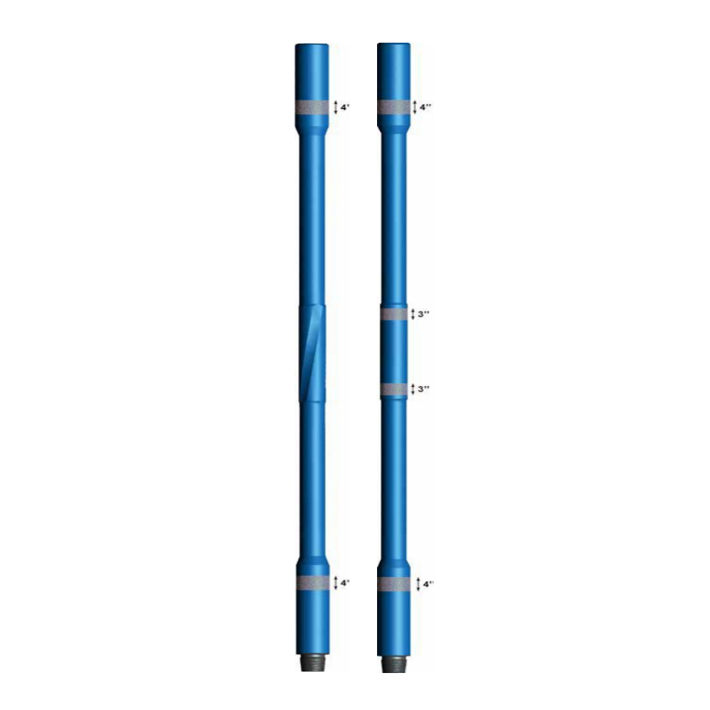
Heavy Weight Drill Pipe (HWDP) is an intermediate weight drill stem component which is used in conjunction with the drill pipes and drill collars. HWDP is available in standard, spiral and nonmagnetic designs. In some applications, heavy-weight drill pipes also can be used instead of the drill collars.
HWDP is made from one-piece AISI 4145H modified quenched and tempered steel. It is designed for tough drilling environment in vertical and directional wells. HWDP is a transition member between drill collar and drill pipe. For directional holes HWDP provides weight on-bit and additional stiffness to prevent buckling.
Features and Benefits
● A center upset or wear pad to increase tube life, reduce hole drag and differential sticking problems;
● Connections are completed (phosphate coated) to protect them from the elements after machining and to help prevent galling upon initial make-up;
● Thread roots are cold rolled on API and H-90 connections. And pressed steel thread protectors are supplied for standard connections;
● Hard banding and internal coating can be provided on customer’s request.
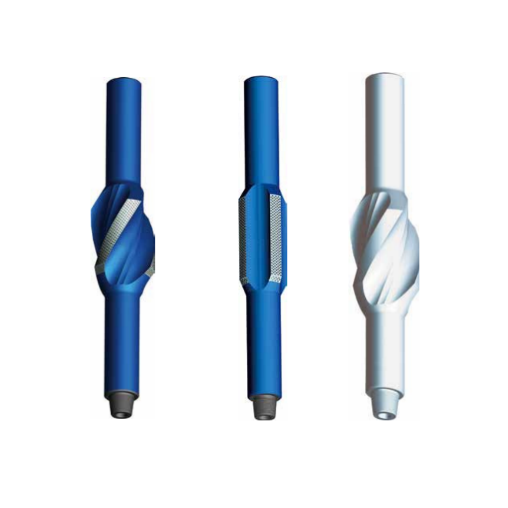
Integral Blade Stabilizer (IBS) is a one piece rotating stabilizer which can be placed near bit or higher in the drill string. It is a one piece construction manufactured from high strength alloy steel (non-magnet steel optional), that prevents differential sticking of the drill string by stabilizing the BHA and keeping drill collars and drill pipes away from the borehole wall. This reduces vibration, drill pipe whirl, and wellbore tortuosity; furthermore, the stabilization maintains drilling trajectory whether drilling straight, horizontal, or directional wells.
Optional Stabilizers
Offers several options for IBS, in both alloy steel and non-magnet materials:
● Spiral Integral Blade Stabilizer;
● Straight Integral Blade Stabilizer;
● non-Magnet Integral Blade Stabilizer;
When ordering please specify:
●Hole size or required blade O.D.;
●Number of blades required (3 or 4 are standard styles);
● Straight or spiral blades;
● Hard facing type;
●Top and bottom connections;
● Body diameter required;
● String or near bit application;
●Alloy steel or non-magnet materials;
● Special features SRG on connections, bored for float etc.
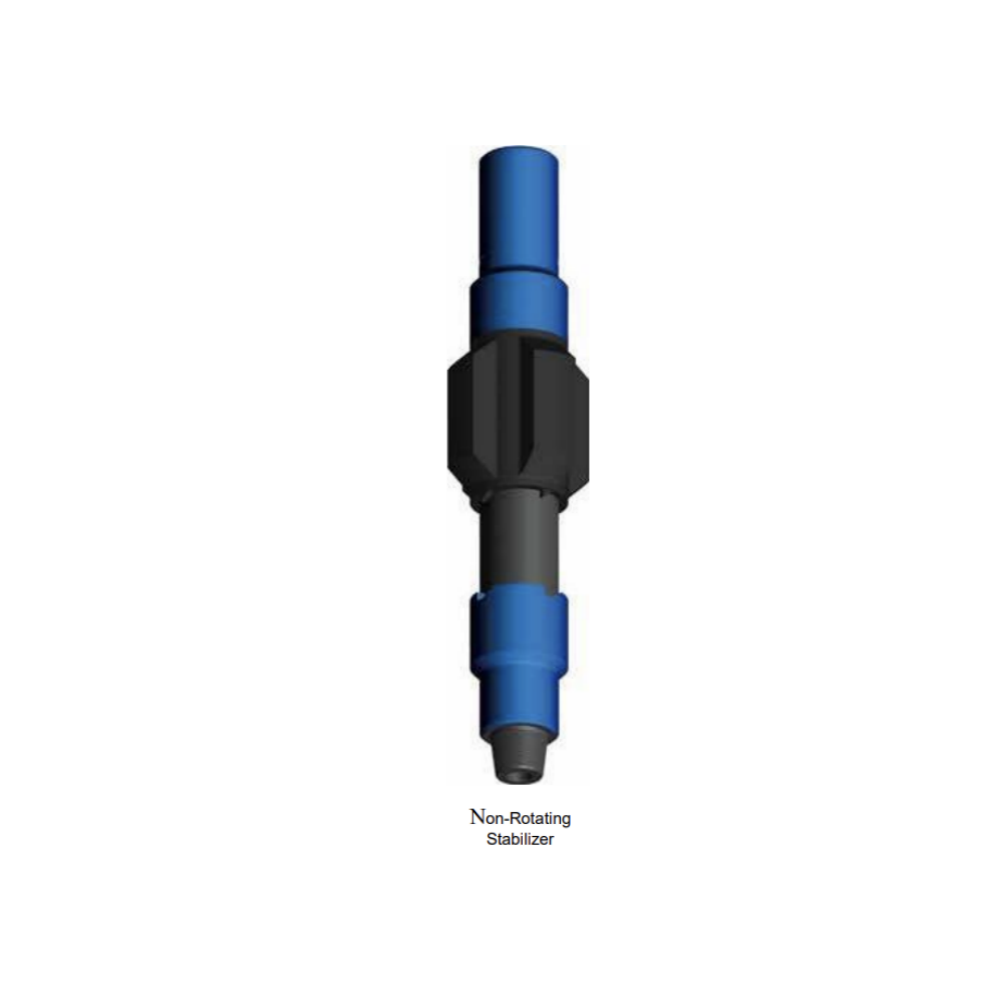
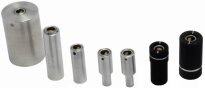
Non-rotating stabilizer (rubber sleeve stabilizer) is able to avoid blade wear and wall damage during drilling. The non-rotating stabilizer consists of mandrel, copper washer, rubber sleeve, spacer sleeve and self-locking lower sub. During drilling, the non-rotating stabilizer transfers the torque by means of mandrel. The rubber sleeve is sliding and moving relative to the mandrel and it plays a role in stabilizing the well. A locking clutch (self-locking lower sub) will help to avoid sleeve rotation during was hover operation.
When ordering please specify:
● Casing size and weight;
● Hole size or required blade O.D.;
● Top and bottom connections.
We offer a complete range of Hard Facing to suit all drilling conditions. All Stabilizers can be banded with the following hard facings.
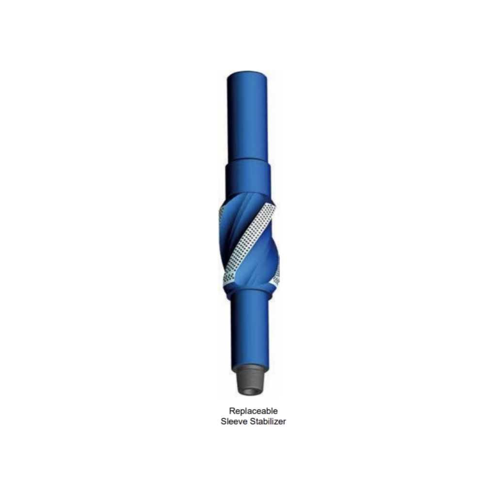
Replaceable sleeve stabilizer consists of an integral mandrel and a sleeve. One mandrel series can be equipped with different sizes of sleeve for several hole sizes. In order to match the drilling conditions, the sleeves can be easily changed on the rig floor during changing of hole size or wear surface.
When ordering please specify:
● Mandrel series and sleeve O.D.;
● String or near bit application;
● Top and bottom connection;
● Hard facing type.
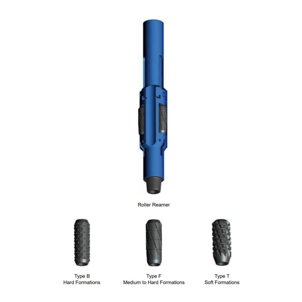
Roller Reamers are designed for reaming and stabilization in any type of formation. All parts of the tool are made of special alloy steel and heat treated for hardness. Drilling crews can easily replace any part in the field without using any special tools.
Offers three types of cutters for different type of formation.
When ordering please specify:
● Hole size;
● String type or near bit type;
● Drill collar size;
● Top and bottom connection;
● Type of cutters.
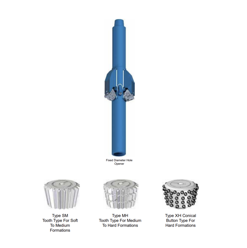
Fixed Diameter Hole Openers are designed for use in soft clays and shales to medium-hard shales and limestones. It is particularly effective in sticky formations where balling problems are encountered. Three jets with replaceable nozzles continuously clean the tool’s cutting structure, clearing debris buildup and increasing penetration.
Fixed Diameter Hole Openers are used in the following conditions:
1.When drilling of a big hole is not possible because of rig capacity.
2. When a satisfied penetration rate is not obtained when drilling a big hole, it is used after drilling is completed with a smaller bit.
3. When the hole direction must be controlled.
When ordering please specify:
● Hole size;
● Pilot hole size;
● Top and bottom connections;
● Fishing neck and bottom neck O.D and length;
● Type of cutters.
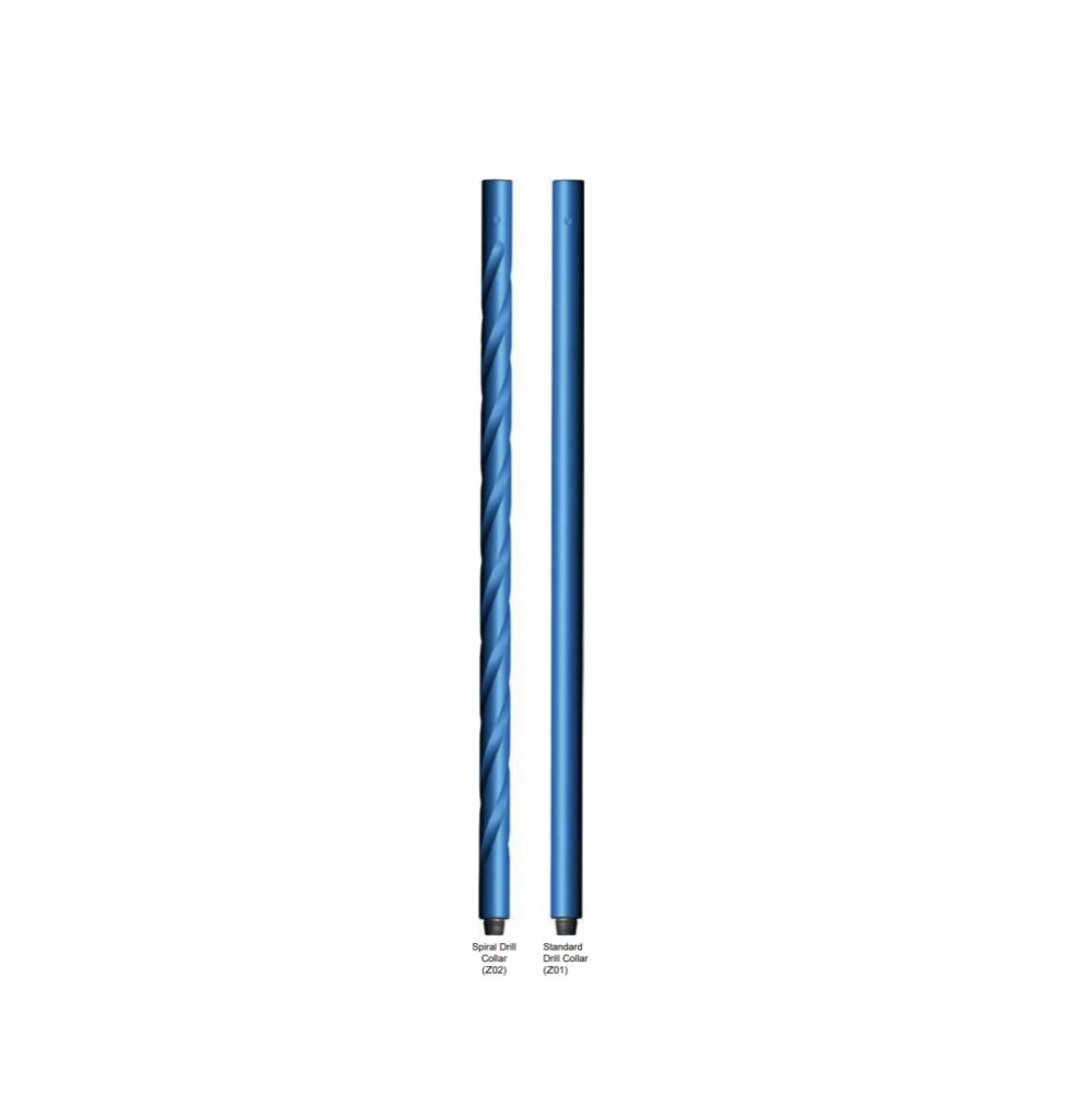
Drill Collar is the basic component in the BHA which provides weight on the bit for drilling and keeps the drill string in tension.
Drill Collar is manufactured from AISI 4145H modified quenched and tempered steel and is heat treated along its entire length for uniform toughness and durability. Strict metallurgical tests are performed per specifications to ensure that the heat treatment produces consistent and maximum hardness through the depth of the bar.
Describe
Features and Benefits
● A hardness range of 285 to 341 BH N and a Charpy impact value of 40 lbs./ft are guaranteed for evenly distributed 16 points in any cross sections at room temperature;
● Connections are phosphate coated after machining to protect the threads from corrosive elements and to prevent galling upon initial make-up;
● Thread roots are cold rolled on API and H-90 connections;
● Pressed steel thread protectors are supplied for all drill collar that are equipped with standard connections
When ordering please specify:
● Drill collar OD and ID;
● Overall length;
● Connections required (size and type);
● Special features desired, for example: Slick or Spiral; Stress Relief Features; Slip and/or Elevator Recess; Hard banding;
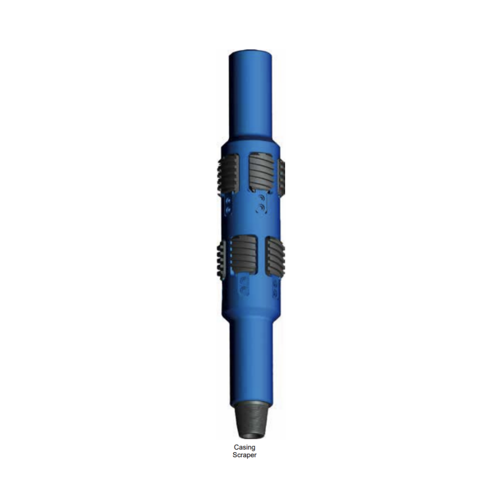
During drilling, fishing, completion or wireline jobs, it is critical for the downhole tools to have a obstruction-free casing so as to increase efficiency. Casing Scraper removes rust, scale, cement, mud, bullets, par
Maintaining a clean casing is important during drilling operation, fishing or wireline tools. Likewise, packers, patches, spears, and similar tools require clean surfaces to grip. Obstructions on casing walls frequently cause these tools to fail or become difficult to operate.
Our Casing Scraper removes deposits, burrs, and irregularities from casing that might cause trouble during the operation of packers or other close tolerance equipment.
Casing Scraper has two sets of blades. Each blade is constructed using high quality cast steel for excellent scraping characteristics and long-lasting durability. These scraper blades are designed to scrape over 360º of surface area. The scraper blades are designed with a long taper for passing through casing connections with minimal chance of hanging up.
Operation
The Casing Scraper is normally connected to the work string with a drill bit attached at the bottom. Simply run the scraper into the casing or tubing using rotation or spudding to clean the inside wall of the pipe.
When ordering please specify:
● Casing Scraper model;
● Connection, if non-standard;
● Casing size and weight.
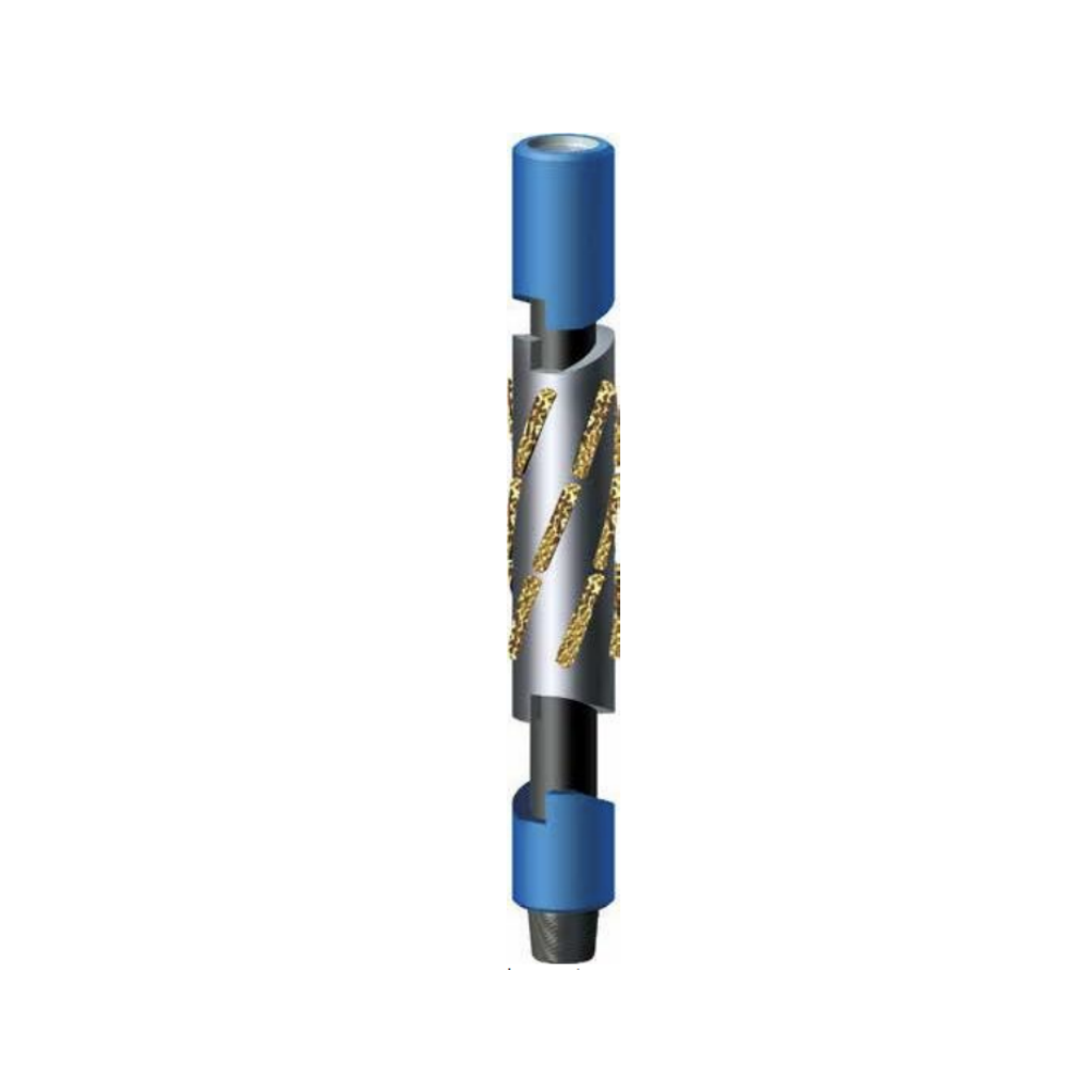
The key seat reamer is a sleeve with five blades dressed with an aggressive tungsten carbide hard facing. Key Seat Wipers are most effective for reaming out key seats when pulling out of the hole using the single-clutch ascent type, or using the double-clutch dual-action ascent-descent type when reaming in and out of the hole.
Running key seat reamer will save you from costly fishing jobs and downtime.
Describe
Operation and application
The key seat reamer is placed in the string between the drill pipe and the drill collars. During drill ahead operations, the non-rotating sleeve will not ream the formation. In case of over-pull -- when tripping out drill collars or reaming back to shoe through a dogleg – rotate the drill string while pulling out of hole to cause the clutch ring to transmit rotation to the wiper sleeve and initiate reaming operations.
The reamer blades will enlarge the key seat to allow the passage of the bottom hole assembly through potential tight sections of the hole.
When ordering please specify:
● Upper and lower neck diameter;
● Upper and lower connections;
● Circulation bore;
● Drill collar O.D. or gauge O.D. of wiper sleeve at blades
Rotary Subs are made from AISI 4145H modified quenched and tempered material. In addition, it is designed and manufactured according to API specifications as well as with API monogram. They can be used to crossover from connection size to another or as a disposable component used to extend the connection life of a more expensive drill stem member.
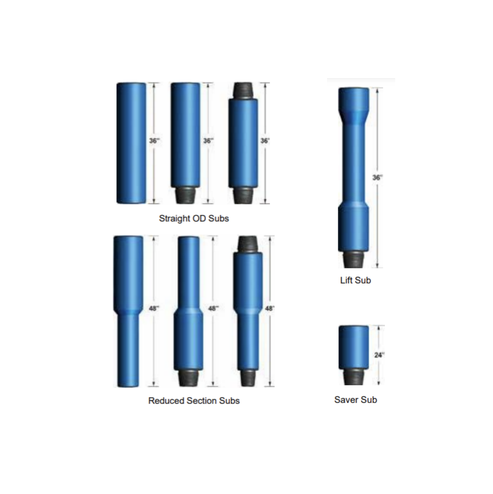
Lift Sub
A lift Sub enables safe and efficient handling of straight OD tubulars such as drill collars, shock tools, jars, directional equipment and other tools by using the drill pipe elevators.
Saver Sub
When rods is added to increase the depth of drilling, the loosening of the threads are now performed at the bottom end of the Saver Sub as opposed to the bottom of the Kelly which is the most valuable part of the drill string. This means that the connection between the top end of the Saver sub and Kelly is seldom used, and suffers minimal wear and tear, whereas the lower connection is used in almost all cases displacing the most wear and tear from the rotary head connection to the much cheaper Saver Sub which is expendable and reduce cost.
Straight OD Sub
Straight OD Sub is used to connect drill stem members that have a similar outside diameter. The drill bit, downhole tools, heavy weight drill pipe and drill pipe can be crossed over using a straight OD sub.
Reduced Section Sub
Reduced Section Sub is used to connect drill stem parts that have different diameters. This sub can be used to crossover large OD drilling tools or a tapered drill collar string.
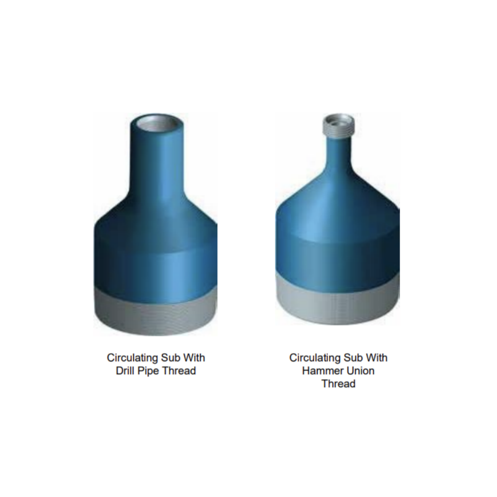
The Circulating Sub is connected between wellhead pipe string and ground circulating system. When casing is running or completed, the circulating sub can be connected to provide fluid circulation. According to the application, circulating s
Construction
The circulating sub during running casing is equipped with casing pin thread on one end and DP thread, DP box thread or union thread on the other.
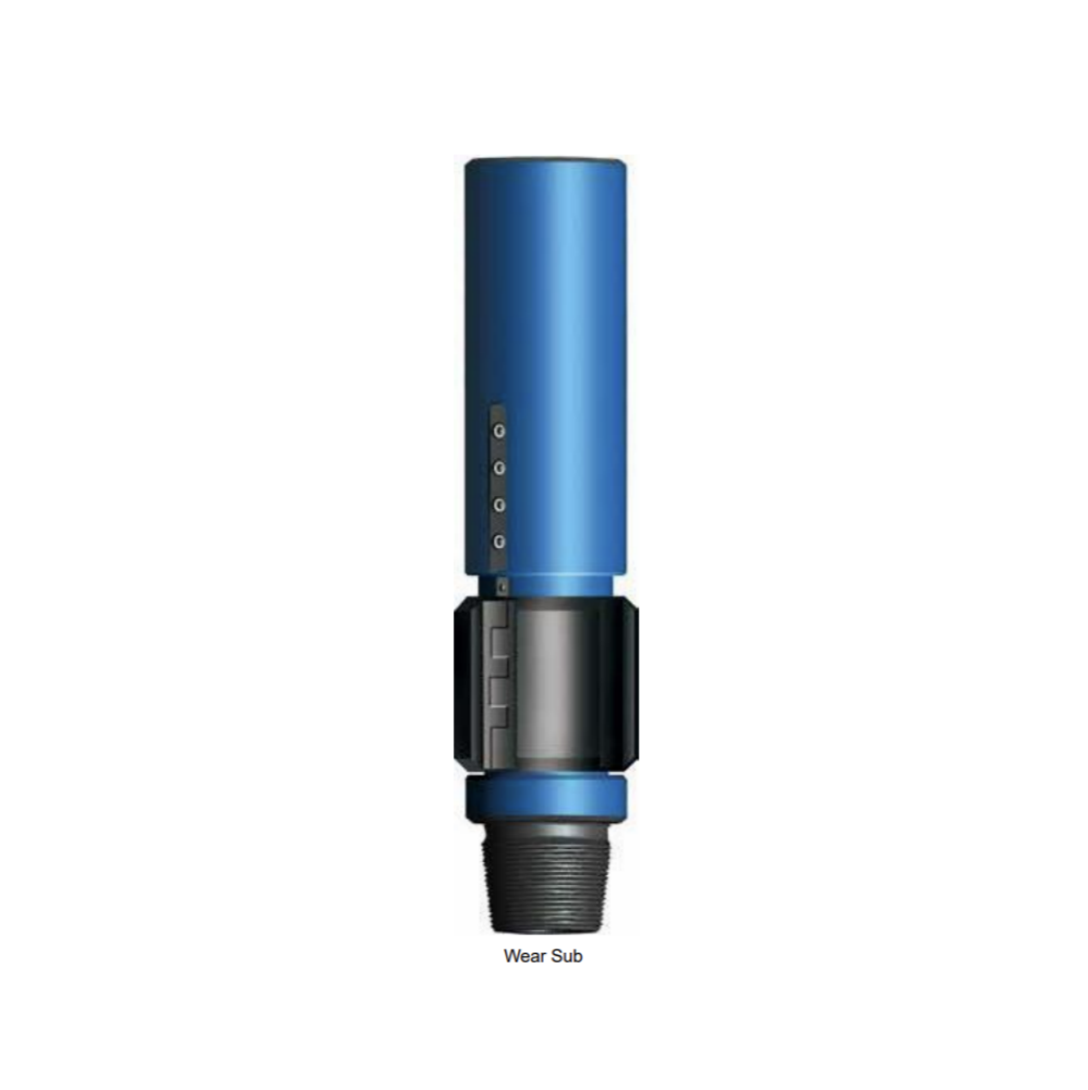
During drilling operation, major wear and tear wear often take place between drill pipes and casings. Wear Sub is used to avoid the wear between drill pipes, tool joints and casings. With features such as compact structure and easy operating, Wear sub can prolong the service life of drill pipe and casing and reduce the vibration and trembling of drilling tools. It can also limit the contact friction between metals.
Wear sub consists of a highly wear rubber sleeve, a metal stiffening liner and a sub body. The rubber sleeve is installed in the middle of sub body and some clearance is given to allow sleeve to rotate freely. The rubber sleeves are made of rubber mixtures with good wear resistance.
During drilling operation, the rubber sleeve and sub body can make a relative rotation. The rubber sleeve O.D is larger than drill pipe tool joint O.D, therefore the tool joint and drill pipes cannot come in contact with casing. The rubber sleeve on saver sub will first contact with casing. When friction between rubber sleeve and casing takes place, wearing can be reduced due to the rubber sleeve wear resistance and softness. Usage of tool joints of drill pipes and drill string tools will also be reduced.
When ordering please specify:
● Casing size and weight, or O.D of wear sub;
● Connection
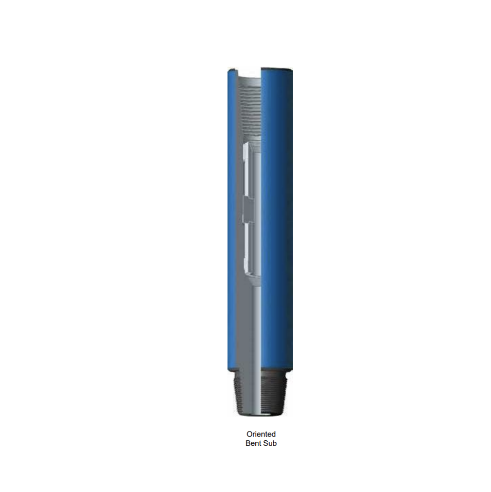
The oriented bent sub is a major power deflection tool having a fixed angle deviated from the low end thread of the bent sub to the axial line of drill stem. Under the application of oriented bent sub the power drill tool give the bit a constant lateral force to ensure that the bit can cut on the well wall laterally and further drill into a curved well trace.
Operation method
● After the bit and oriented sub are connected and screwed, measuring of the angle between the nozzle of bit and oriented key of oriented bent sub shall be done;
● After run in drill tool, calculate out the azimuth of nozzle of bit according to the azimuth of oriented key determined at a single point by drift indicator;
● Change the nozzle of the bit into required azimuth, then lock in rotary and start pump drilling to cut in;
● During deflecting, using this approach that deflects while lightly pressing and crowning the drill to help deflection; ● After deflected for 2 to 3 meters, drill in 4 to 5 meters with light pressure and slow rotation;
● Repeat above mentioned operations for several times, when the angle of deviation is up to the expected requirement deflecting in can be done smoothly by reducing drill pressure and increasing rotation speed.
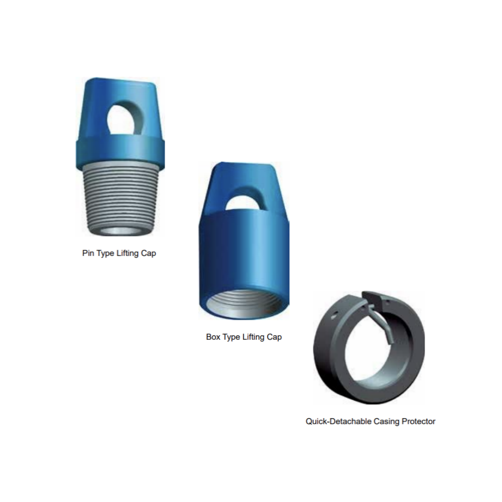
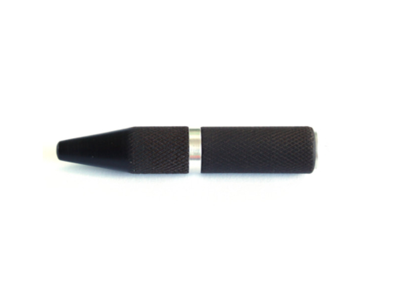
Lifting caps are tools for lifting of drilling tools, such as drill collars or stabilizers.
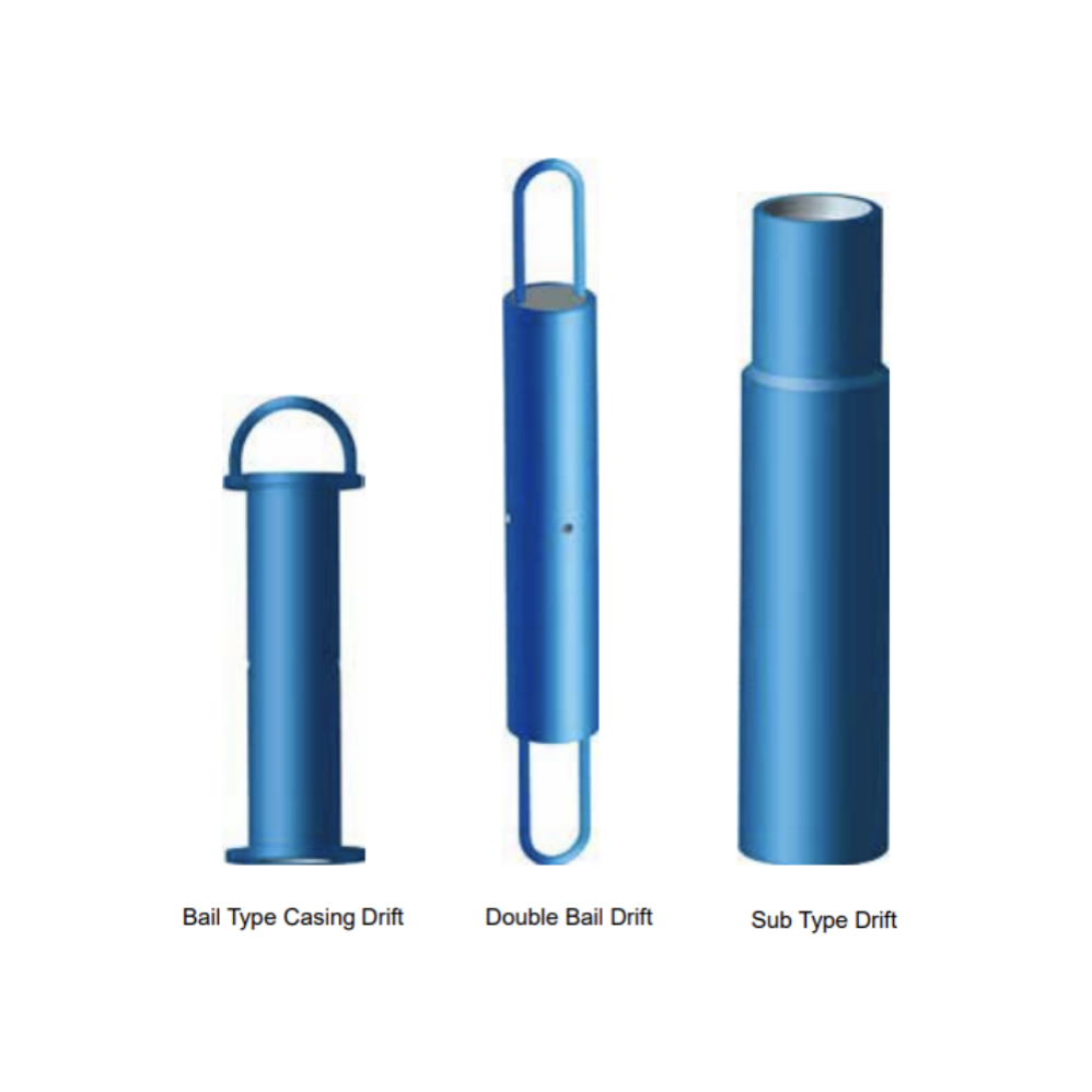
Drift is a simple and popular tool for drifting I.D. of casing, tubing, drill pipe and other pipes. It is used to check whether inside diameter of all kinds of pipes are complied with standard, and to determine the max. inside.
Drift for casings are available in two types:
Sub Type Drift manufactured with threads on both top and bottom ends. The top end is connected with the drill string, while the bottom end is standby.
Bail Type Drift comprises of gauge plate and connecting rod.
Double Bail Drift for tubing or drill pipe is usually used on the ground. The shape of drift diameter gauge is a long cylindrical body with sucker rod thread on both ends. Drifting is done manually.
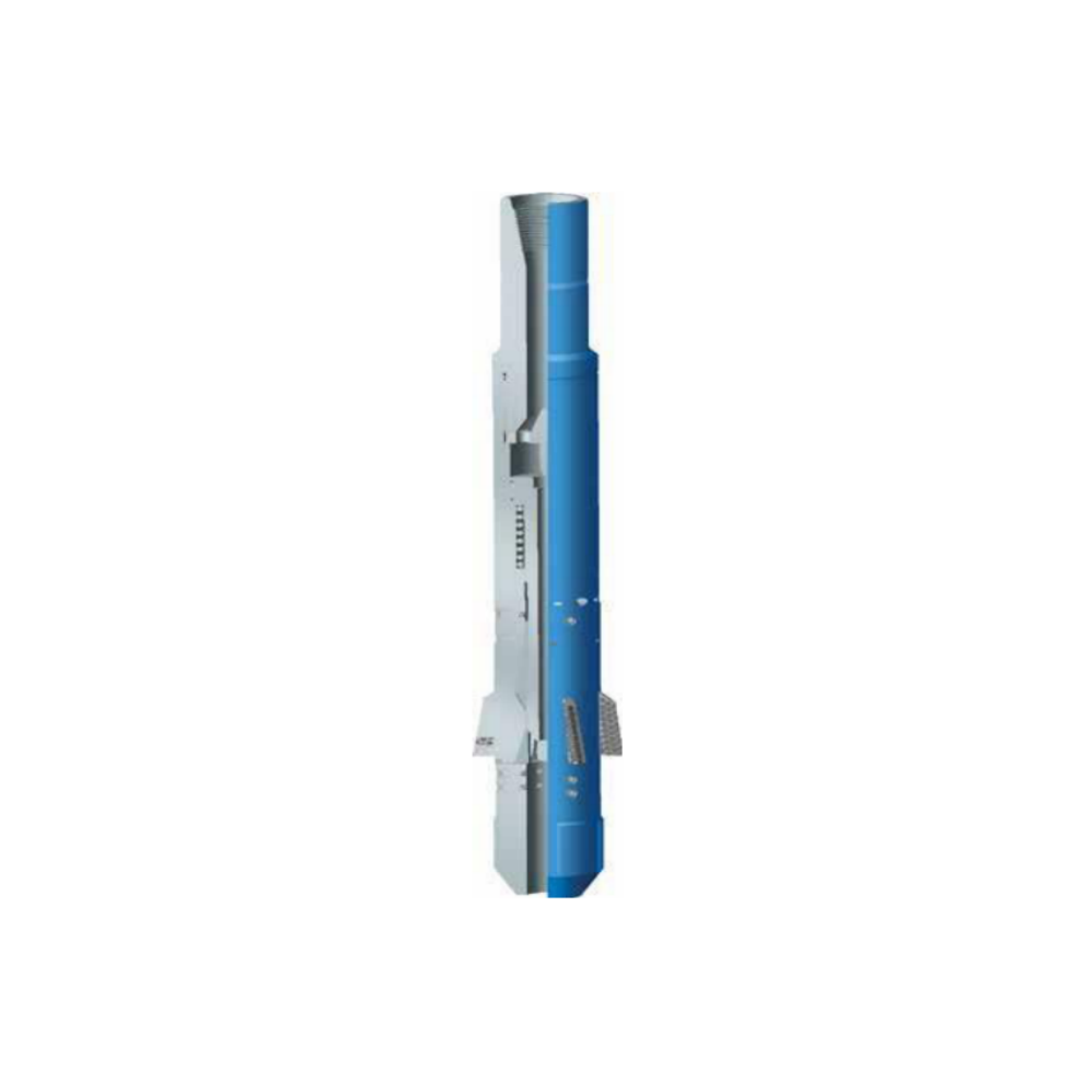
YTQC type string magnetic is one of the auxiliary tools to ensure normal drilling operation and bottom hole cleaning after downhole accident treatment. The main feature of this product is that it works together with the junk mill in the fishing operation, which is different from the previous practice of lifting the drill after milling, and then connecting the drill string with the strong magnetic fishing device to go down the well for bottom hole cleaning, saving a trip down the well, which saves both drilling costs and fishing time.
Working principle
Main working principle: during milling and fishing operations, the debris at the bottom of the well is under the action of slurry circulation, it will be adsorbed on the strong magnetic field body of the drill string, and these debris will return to the ground from the bottom together with the strong magnetic field of the drill string, so that the bottom hole can be cleaned at any time during milling operation.
Section mills are primarily used to milling sections in the casing (for side tracking, gravel packing)
and perforation zones. Section mill is available in a variety of Casing sizes, ranging from
4 1/2" to 13 3/8". The blades are all dressed to enable simultaneously milling of the casing. The milling rate is usually limited by the ability of the fluid in removing the cuttings.
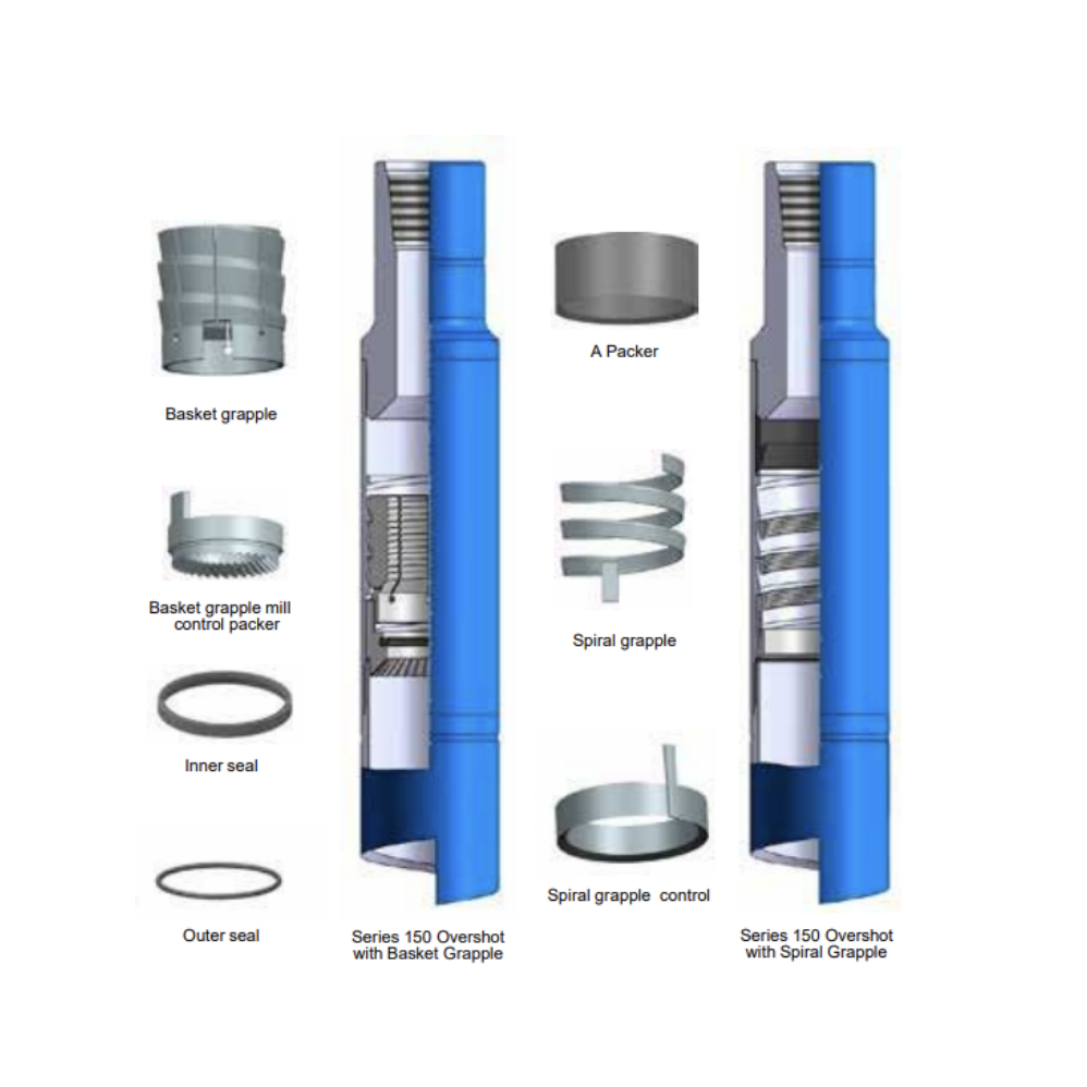
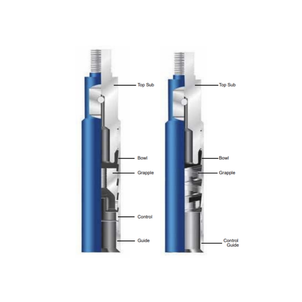
Series 150 Releasing and Circulating Overshot is an external fishing tool for engage, pack off and retrieve tubular fish, especially for fishing drill collar and drill pipe. The grapple of the overshot can be designed for different sizes of fish, so one overshot can be dressed with different size of grapple components for fishing different sizes of fish.
Construction
Series 150 Overshot consists of three outside parts: Top Sub, Bowl, and Standard Guide. The Basic Overshot may be dressed with either of two sets of internal parts, if the fish diameter is near the maximum catch of the Overshot, a Spiral Grapple, Spiral Grapple Control, and Type “A” Packer are used. If the fish diameter is considerably below maximum catch size (½” or more) a Basket Grapple and a Mill Control Packer are used.
When ordering please specify:
● The model of the overshot
● The hole, casing size or O.D. of overshot
● Top connection
● O.D of the fish
FS = Full Strength
SH = Slim Hole
Series 10 Sucker Rod Overshot is a professional fishing tool, designed for engaging and retrieving sucker rods, couplings, and other tubular from inside tubing strings.
Engaging a Fish When overshot nears the top of the fish, slowly rotate to the right as the overshot is lowered over the fish. After the fish is engaged, allow right-hand torque to release from the fishing string. Then raise the fish by pulling upward on the fishing string.
Releasing a Fish Bump down or drop the weight of the fishing string against the Overshot to break the hold of the grapple within the bowl. Elevate the fishing string while slowly rotating it to the right until the Overshot has cleared the fish.
Type DLT-T Releasable Reversing Overshot, a new type of fishing tool, has many advantages owned by various overshot, box tap and the like. Its distinguishing features are as follows: to unscrew and recover the stuck fish; To release the fish down hole if necessary; to circulate the washing fluid as one of the accessories for reversing tools. It is widely used in well servicing.
Structure and Application
Consisting of top sub, spring, bowl, retaining seat, slip, control key, seal ring, seal seat, guide and so on. The upper end of top sub is connected with other tools and drill tool. The lower end of top sub is connected with bowl equipped with spring in the interior. There are three control keys uniformly distributed in the inner wall of the upper end of bowl. the control keys are used to control the position of retaining seat. Three keys are inserted separately in three grooves in the tapered interior section of lower end in bowl where three keys are used to transmit torque. The tapered interior section produces a pinch force against the slip to trigger the fishing operation. The inclined angle among three control keys play an important role in retaining conformance of the slip with the bowl to ensure that the tools can be released easily from the fish.
The retaining seat is installed at the upper end of the external bowl where the three keys are placed. The retaining seat not only can slide axially, but also rotates round the axial line moving with the slip which is installed in the internal circular recess.
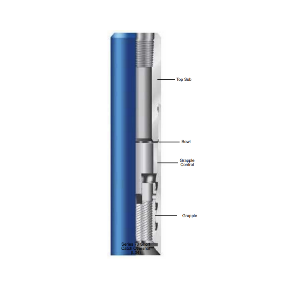
The Series 70 Short Catch Overshot is an external fishing tool designed to retrieve tubular fish when the top of the fish is too short to be engaged with other overshot. The Grapple Control is positioned above the Basket Grapple rather than below it to allow the Basket Grapple to occupy the lowest position in the Bowl. This enables the overshot to firmly engage and retrieve a very short fish.
Construction
The Series 70 Short Catch Overshot assembly consists of a Top Sub, Bowl, Basket Grapple Control, and a Basket Grapple. Although the Series 70 Overshot has no Guide, the components function in the same manner as the standard Series 150 Releasing and Circulating Overshot.
Catching the Fish
Attach the Overshot to the bottom end of the fishing string and run it into the hole. Series 70 Overshot assembly is rotated to the right and lowered as the fish enters the expandable grapple. With the fish in the grapple, stop right-hand rotation and exert an upward pull to fully capture the fish.
Releasing the Fish
A sharp downward force (bump) is applied to the Overshot to break the hold of the grapple within the bowl. The Overshot is then rotated to the right while it is slowly elevated to release the grapple from the fish.
When ordering please specify:
The model of the overshot.
The hole, casing size or O.D. of overshot Top connection
O.D of the fish
note: We can design Overshot according to customers' request
Lifting-Lower and releasing overshot is a fish tool in the casing which fishes fractured tubing and drill string. If fish drill string is stuck heavily and hard to complete fishing work, while need to release fish, may get back the tool by bumping drill string down and lift directly.
The product is excellent for fishing operations as it does not require rotation. Fishes can be caught or released through simple lifting or lowering of the tool.
Describe
Structure
Lifting-Lower and Releasing Overshot is composes of top sub, bowl, guide pin, guide sleeve, joint sleeve, plug, roller pin, slip, guide, as shown in the figure. The box thread of top sub is connected with drill stem and the pin thread is connected with the bowl, The bottom of bowl is connected to the guide. An inner cone in the bowl matches the slip. Box thread of guide sleeve is connected with joint sleeve, track trenches are milled on another outer surface: three long trenches and three short trenches act as guiding and reversing. When guide pin locates in long trench is in the condition of fish. When guide pin locates in short trench is in the condition of release. Joint sleeve is two petals formation. It makes slip and guide sleeve connection and by roller pin act as bearing. The inner surface of slip has fish thread, guide is on the bottom and can make fish introduce into slip successfully.
Working Principle
The tool complete fishing and releasing fish through long, short track trenches. When the tool reaches the top of fish, it is lowered and is in contact with the fish. Through lifting and lowering, guide pin is in the position of long or short trench, slip is in the situation of fishing or releasing, in the condition of non-rotating complete fishing and releasing fish.
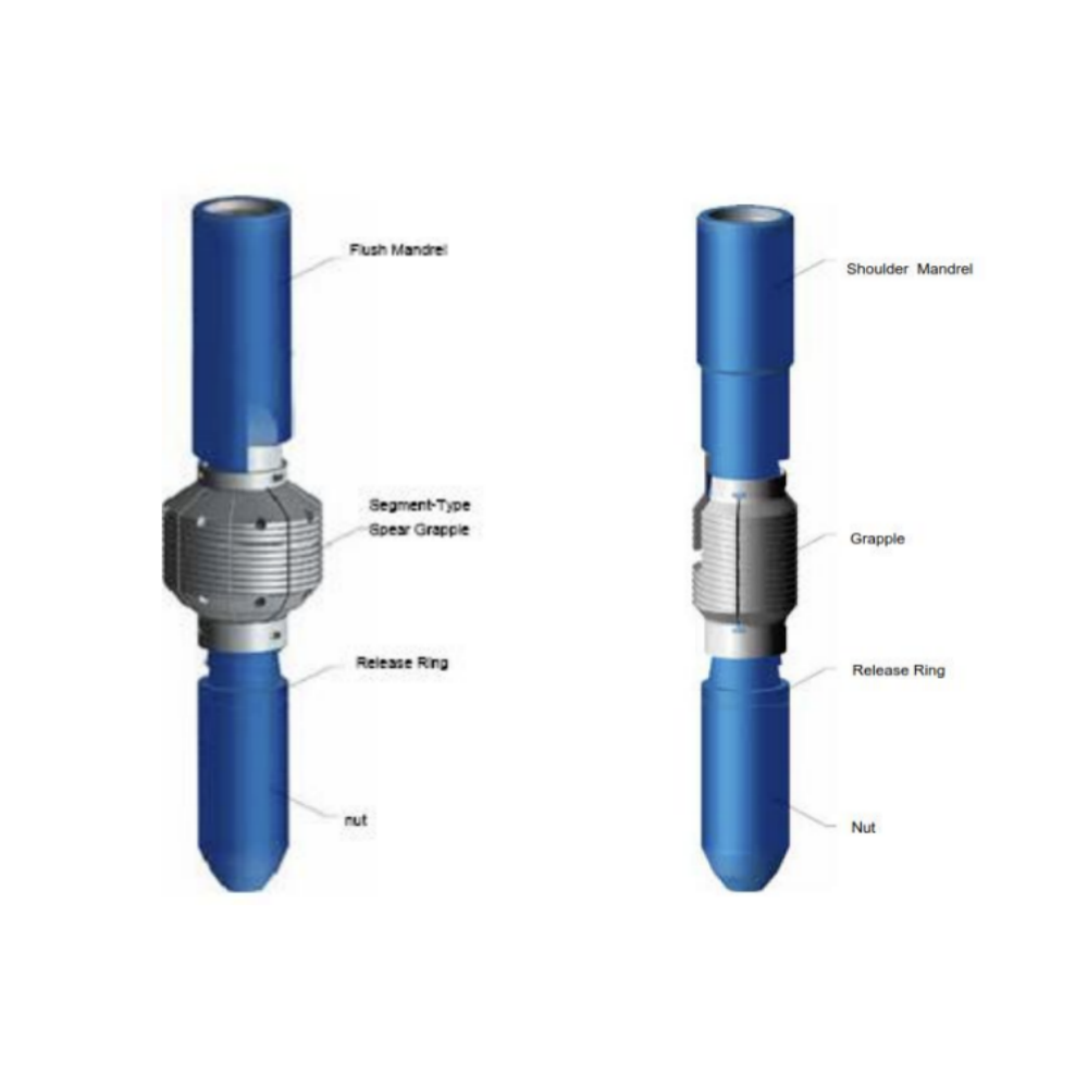
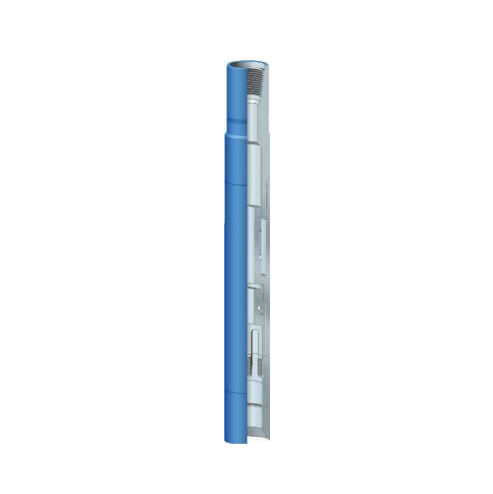
Releasing Spear provide a more effective means to engage and retrieve an internal fish from the well. It is ruggedly built to withstand severe jarring and pulling strains. It engages the fish over a large area without damaging of the fish. The simple design prevent small parts being lost or damaged in the hole during operation. It may be used with other equipment such as pack-off assemblies and internal cutters. If the fish cannot be pulled, the spear can be easily be released and disengaged.
Construction
The Releasing Spear consists of a mandrel, grapple, releasing ring, and a bull nose nut. The mandrel is made of specially heat treated high strength alloy steel; and may be ordered either as a flush type to enter completely into a fish or as a shoulder type to provide a positive landing position on top of the fish. Size and type of the upper box connection can be customized provide according to customer’s exact specification.
When ordering please specify:
● The model of the releasing spear.
● Top connection
● The exact size and weight of the fish
● Flush or shoulder type mandrel
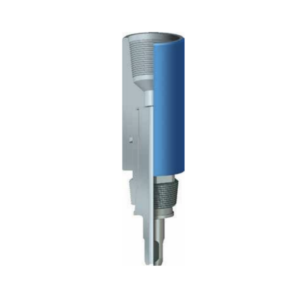
The reversing subs is also called reversing spear which is a special tool for reversing stuck drill stem above stuck point in drilling and workover operation. In treatment of stuck drill stem, it can work as a fishing pin tap in reversing operation. When fish is stuck or cannot be reversed in fishing or reversing operation, the fish can be reversed from reversing sub and the fishing drill tool is tripped out.
Specifications - Reversing Sub
Table 1. DKJ Reversing Sub (thread connection LH, catch thread RH)
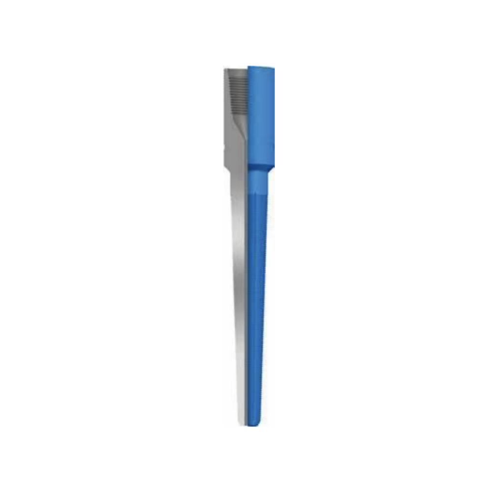
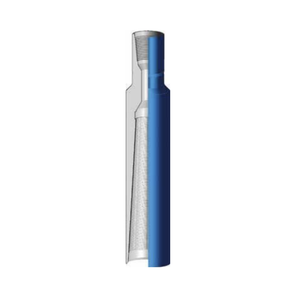
The die collar, also known as skirted taper tap, is a special external fishing tool that engages with the dropped tubular objects such as drill pipes and oil tubing, by tapping on the external wall of the objects. It can be used in fishing cylindrical objects without inner bore or stuck inner bore.
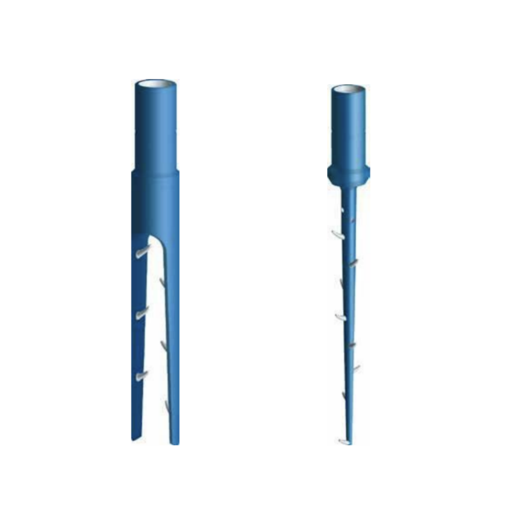
The internal hook is a fishing tool generally used inside casings and oil tubings for fishing ropes and other fishes such as wire-lines, cables, logging wire-lines and paraffin cutters.
There are two types of internal hooks for different fishing applications: Dead (fixed) hook and Live (adjustable) hook.
The External Hook is used inside casings and tubing's to catch all kinds of ropes, lifting bails, hollow short cylinders, short rope slings such as wire-lines, logging steel pieces, cables, etc.
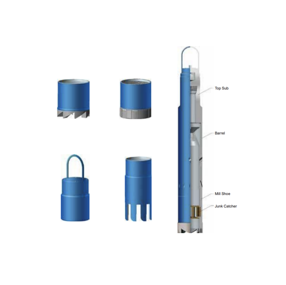
Reverse Circulation Junk Basket (RCJB) is designed to remove all types of small junk objects from the well hole. The tool’s main feature is that it eliminates the possibility of pulling a wet string during fishing operation with its reverse drainage design. The RCJB can also be used as a fish magnet when fitted with a magnet insert, while maintaining its reverse fluid circulation feature.
Operation
RCJB is normally attached at the bottom of the fishing string, lowered to a point several feet from the bottom of the well. Begin circulation of the junk basket to wash the hole. Stop circulation and drop the steel ball. (When the steel ball is dropped into the valve seat, reverse fluid circulation is activated. The fluid travels outward and downward through the inner passage of the barrel and out through the vents in the lower end. The fluid is then deflected to the center of the tool and up through the return holes in the upper end of the barrel. The reverse fluid circulation carries the junk into the barrel above the junk catcher. Restart the circulation; slowly rotate the junk basket while lowering the tool until a 10-inch core has been cut. Stop rotation and circulation and pull the tool and junk from the hole.
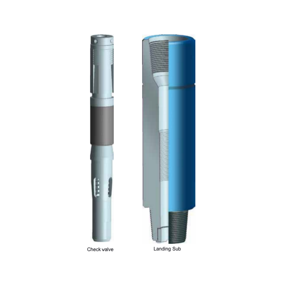
Drop-In Check valves prevent return flow during a kick and are suitable for most drilling situations in which return flow through the drill string is a risk and normal operation requires the benefits of a full-bore sub. By preventing upward flow through the drill pipe and allowing fluid to be pumped downward to circulate the well, the valves provide the driller with the means to control the drill pipe pressures when required, significantly improving and simplifying well control.
Drop-In Check valves prevent return flow during a kick and are suitable for most drilling situations in which return flow through the drill string is a risk and normal operation requires the benefits of a full-bore sub. By preventing upward flow through the drill pipe and allowing fluid to be pumped downward to circulate the well, the valves provide the driller with the means to control the drill pipe pressures when required, significantly improving and simplifying well control.
When a blowout is about to happen, the thread connections of the Kelly is screwed out immediately and a check valve is placed into the drill pipe and then pumped downward to the required place. Thus the blowout can be prevented.
When ordering please specify:
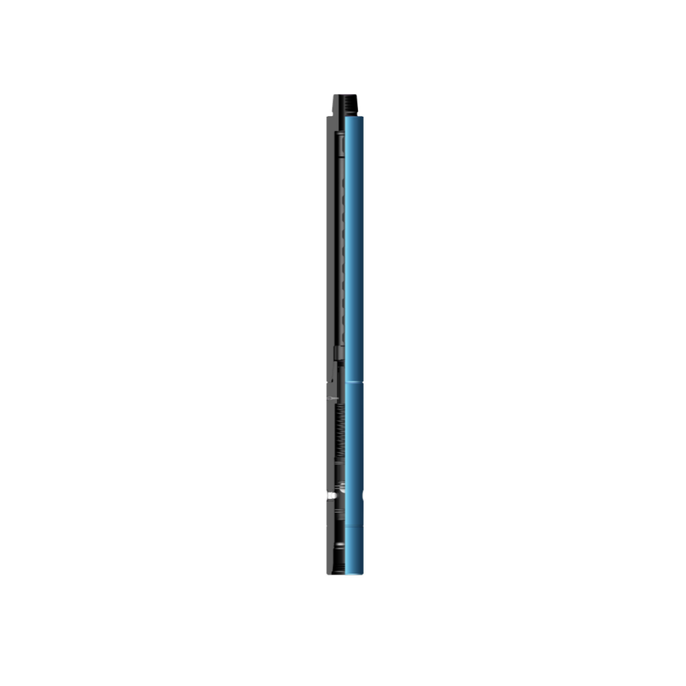
The multiple activation by-pass valve is a set of short circuit that can be opened and closed for many times. It is generally installed in special drilling tool assemblies such as directional drilling, speed raising, logging while drilling, etc. It can open and close the bypass hole in time for special operations according to downhole working conditions, enhance the applicability of special drilling tool assemblies, improve production efficiency, and reduce well control risks.
Advantages
Application fields
1) High concentration and large particle plugging materials and cement squeezing plugging construction shall be carried out without tripping out;
2) Special construction of pumping other corrosive liquids;
3) High displacement well flushing in directional wells, horizontal wells and highly deviated wells;
4) Clean casing and BOP stack;
Basic structure
The multiple activation bypass valve is mainly composed of three parts: by-pass nipple, ball blue nipple and switch ball set. A switch ball group comprises an activation ball, two closing balls and a locking ball. The activation ball and locking ball are made of a new type of engineering plastics, and the closed ball is made of standard bearing steel ball.
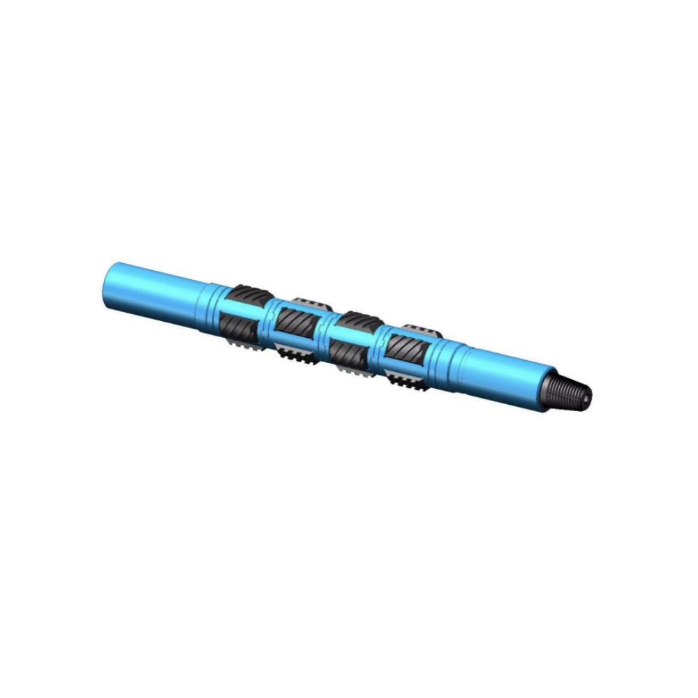
The non-rotating casing scraper is one of the indispensable auxiliary tools for well completion, testing and downhole operations. Its main purpose is to remove cement, sand, scratches, paraffin, burrs and other attachments on the inner wall of the downhole casing, protect the cleanness of the inner wall of the casing, and facilitate the normal operation of all drilling tools.
Advantages
Each set of products is composed of four rows of cutter plates, which can realize 360 degree all-round non-dead angle scraping. The cutter plate does not rotate with the drill string, and only moves up and down relative to the inner wall of the casing, without rotating movement, so the casing will not be damaged.
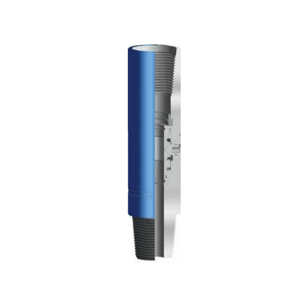
Kelly valve is a manually operated ball type valve for the drill stem, divided into upper and lower sections. The upper Kelly valve is connected between lower end of swivel and upper end of Kelly. The lower Kelly valve is connected between upper end of drill pipe and lower end of Kelly or lower end of Kelly saver subs. The Kelly valve can be opened or closed off by simply turning a special operating wrench 90° according to indicated direction.
The sealing principle for Kelly valve is to ensure a close seat between the ball and the ball seat. The lower seat is supported by a spring. The force provided by the spring keep the ball securely in place with lower seat. During normal drilling operation, the hole is kept unblocked by turning the stem to “on” position; In case of kick or blowout, turn the operating stem to “off” position to close off the internal bore of drill string, the kick or blowout accident is avoided due to a high pressure sealing situation between ball and the ball seat.
When ordering please specify:
● Upper or Lower type;
● Tool OD;
● Working pressure: 5,000 / 10,000 / 15,000 psi;
● Tool connection. Specifications - upper

Full Opening Safety valve (FOSv) is a ball type safety valve used to stop flow through the drill string when the drill string is being withdrawn from the well.
FOSv is a dual body full-opening safety valve, that does not interfere with the running of tools such as core barrels or survey instruments. It is designed to be stabbed into the top joint of drill pipe or tubing string at the rig floor and closed quickly in case a well kicks.
The ball-type design permits the valve to be compact, easy to handle, and have great strength. Standard test pressure is 10,000 psi, but higher pressure ratings are available.
FOSv and operating wrench be should be maintained on the rig floor at all times.
When ordering please specify:
Connection.
O.D. and I.D.
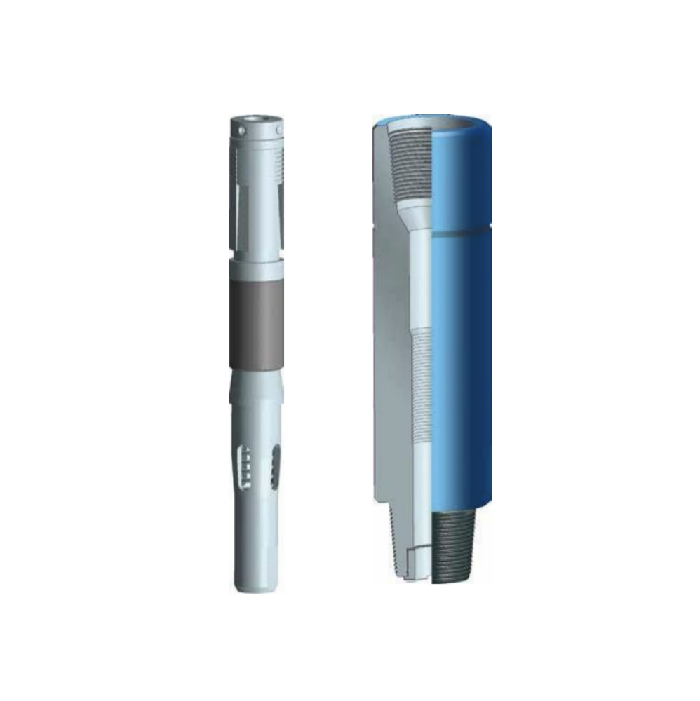
Drop-In Check valves prevent return flow during a kick and are suitable for most drilling situations in which return flow through the drill string is a risk and normal operation requires the benefits of a full-bore sub. By preventing upward flow through the drill pipe and allowing fluid to be pumped downward to circulate the well, the valves provide the driller with the means to control the drill pipe pressures when required, significantly improving and simplifying well control.
When a blowout is about to happen, the thread connections of the Kelly is screwed out immediately and a check valve is placed into the drill pipe and then pumped downward to the required place. Thus the blowout can be prevented. When ordering please specify:
● Smallest bore in drill string through which the check valve must pass.
● Landing sub connection size and type.
● Outside diameter of mating tool joints.
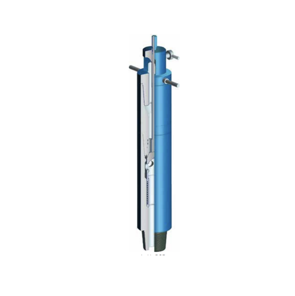
Inside Blowout Preventor (IBOP) is a special tool, which can be stripped through the BOP preempt to be connected with the added drilling tools as soon as possible. When the blowout occurs during lifting operations, the IBOP have many advantages in situation such as, high pressure rating, reliable seal, easy application and operation.
When the drill tool is lifted out of the hole, blowout could happen due to suction. In event of a blowout, the open position of the IBOP valve allows back flow, easing the installation process. Upon successful installation, the valve can be promptly closed with a relief rod to prevent further back flow. Fluid can then be pumped in from the surface to discharge the IBOP and drill string. The purpose of the blowout prevention can be achieved by the following generic steps: discharging the relief sub; regulation of fluid; commence pump circulation.
When ordering please specify the connection of drill string.
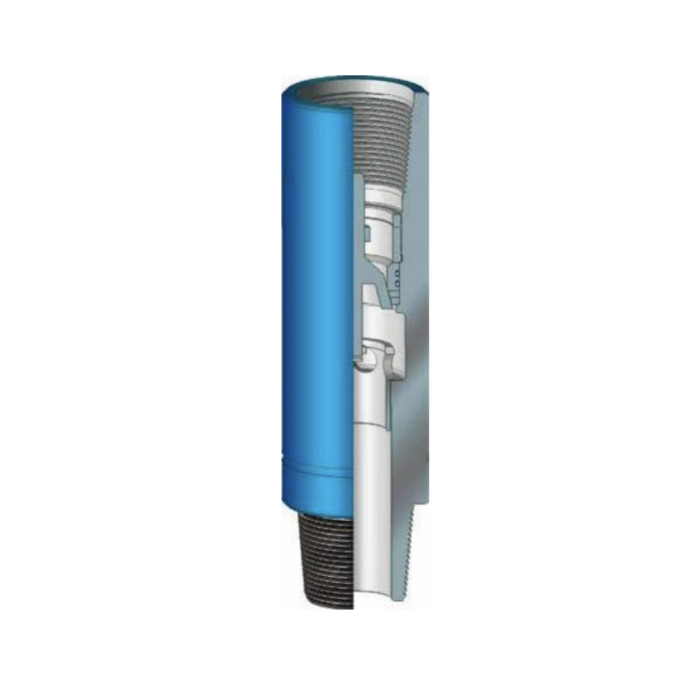
Arrow Type Back Pressure valve is an important tool preventing of blowout.
The design of the Arrow Type Back Pressure valve allows for an on-site determination of back pressure to be set at surface.
Features and Benefits
● Metal to metal sealing;
● Simple design allows easy maintenance. When ordering please specify:
● Size;
● Thread connection.
note: Arrow Type Back Pressure valves are not ideally suited for cementing or abrasive fluids.
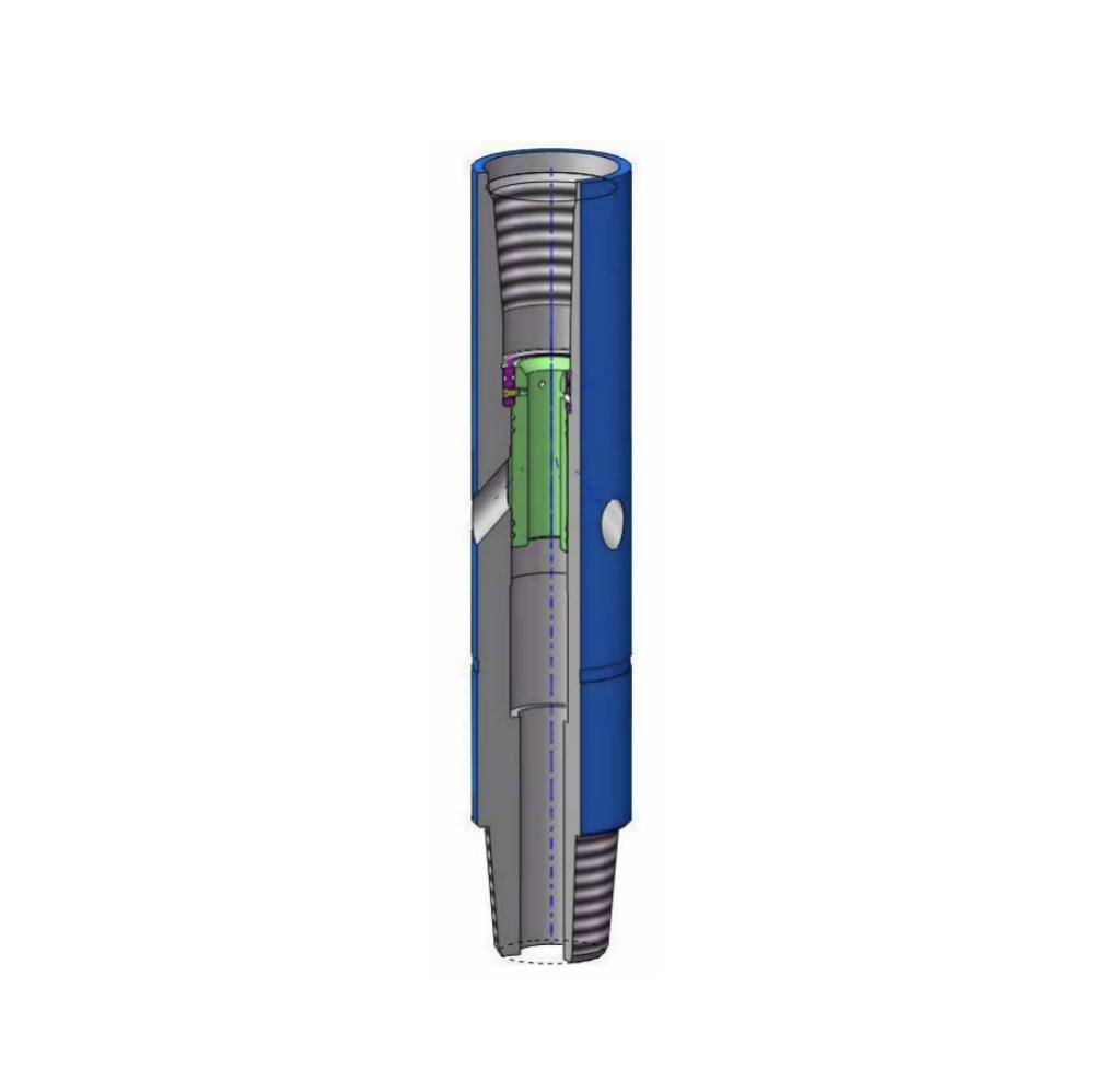
During drilling operation, when a well kick takes place and bit bore is blocked, the by-pass valve can be opened to allow fluid circulation and well killing. Before drilling in a gas formation, the By-Pass valve shall be located near or on the bit.
When well kick take place and pump pressure is too high or blocked, the following steps can be taken to open the By-Pass valve:
● Discharge Kelly and drop in a steel ball (or a nylon ball) which is carried by tool;
● Connect with Kelly;
● Put ball into retainer by pump circulation;
● When fluid is closed, the shear pin can be sheared off by adding 0.5~1.5MPa higher pump pressure than original pump pressure;
● After pin is sheared, the seal sleeve move down to open the discharge hole and pump pressure come to drop down , then normal circulation and well killing operation can be started.
When ordering please specify:
● O.D. of body;
● Connection;
● Pump pressure required to shear off pin (per customer requirement)
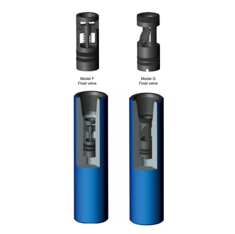
Float valve Sub is an important tool in petroleum exploration and drilling engineering. The float valve sub is connected at upper part of drill bit. The float valve sub is near the bit connecting thread. The float valve sub can also be used at different necessary position of drill string when required. The main application is, when connected with single piece pipe, it prevents mud from coming in and up blocking the hole. When blowout takes place, blowout in drill string will be avoided because nozzle is closed automatically by valve cap of the float valve assembly.
When ordering please specify:
● Float valve type (Model F or Model G);
● Float valve size;
● Connection and O.D of sub.
Cup tester is designed to be attached to the drill string and lowered into the casing beneath the wellhead to test the pressure of the blowout preventer stack and the wellhead. When the cup tester is lowered into the casing beneath the wellhead, pressure is applied to either a test pump or hoisting type cup after filling the hookup with water. This method is fast and accurate.
The Cup Tester assemblies are rated to the API standard mill test pressure for casing sizes up to 10,000 psi. We offer special reinforcing on all cup sizes and casing weight ranges to hold up to 15,000 psi. When ordering please specify:
● Casing size & weight;
● Connection.
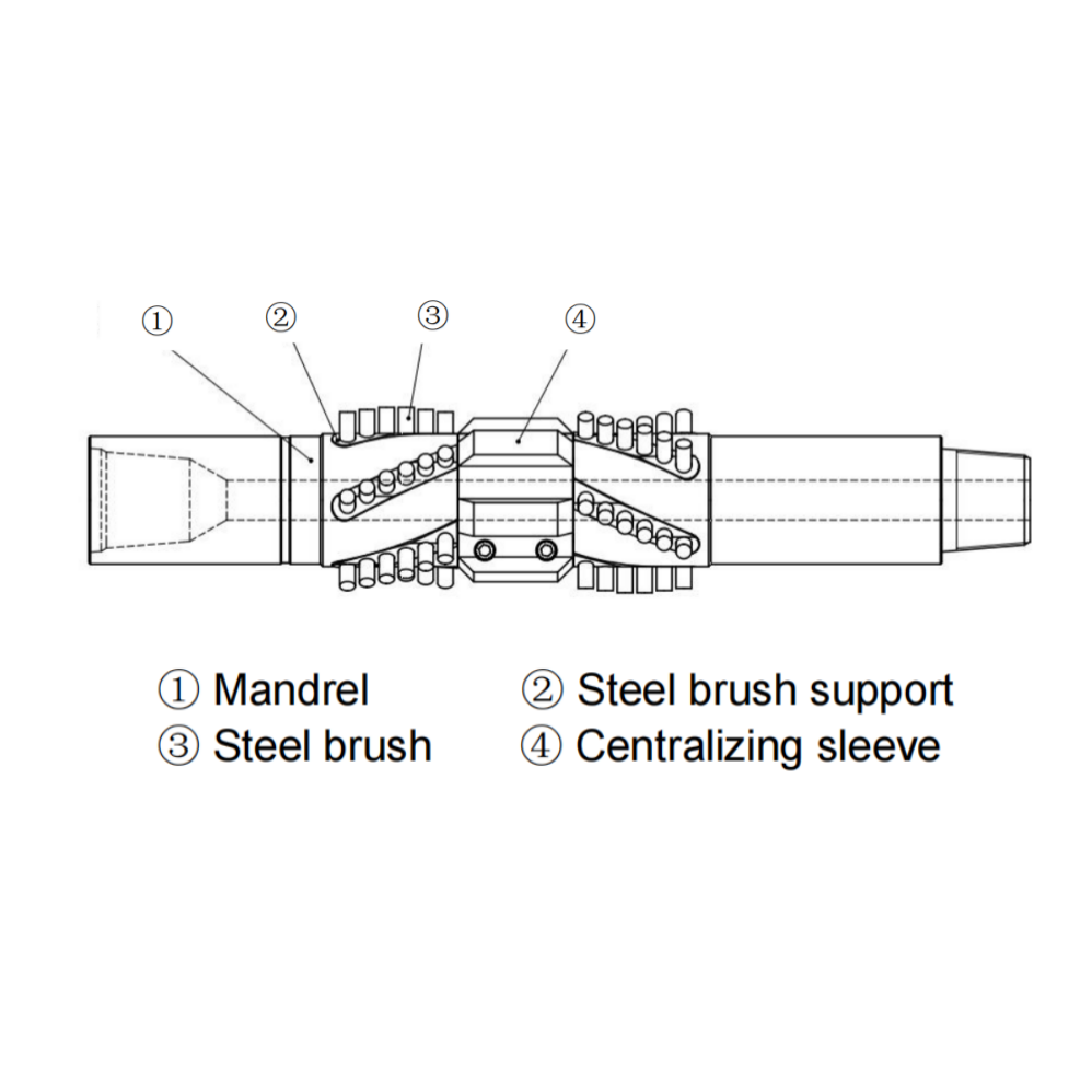
GS (I) Type Casing Brusher is one of the indispensable auxiliary tools for well completion, testing and downhole operation. Its main purpose is to remove the residual attachments after the scraping operation of downhole casing inner wall scraper and protect the cleanness of casing inner wall, so as to facilitate the normal operation of all drilling tools. It is usually used with casing scraper.GS (I) Type Casing Brusher is not suitable for drilling operation.
Product Introduction:
GS (I) Type Casing Brusher is one of the indispensable auxiliary tools for well completion, testing and downhole operation. Its main purpose is to remove the residual attachments after the scraping operation of downhole casing inner wall scraper and protect the cleanness of casing inner wall, so as to facilitate the normal operation of all drilling tools. It is usually used with casing scraper.GS (I) Type Casing Brusher is not suitable for drilling operation.
Product Structure:
GS (I) Type Casing Brusher (Hereinafter referred to as casing brusher) is composed of mandrel, centralizing sleeve, steel brush support, steel brush, etc. The centralizing sleeve is installed in the middle of the mandrel. The diameter of the centralizing sleeve is slightly smaller than the inner diameter of the casing. It can rotate freely on the mandrel and play the role of centralization when cleaning the inner wall of the casing. Select the center sleeve and steel brush with corresponding size according to different casing inner diameter.
Construction and Principle:
After cleaning the inner wall of the casing with the casing scraper, because the scraper is rigid, there will be a small gap between the scraper and the inner wall of the casing, and some attachments will remain after the scraping operation. At this time, the casing can be further cleaned with a Casing Brusher. The steel brush has toughness and can fully contact the inner wall of the casing to brush the inner wall of the casing; The centralizing sleeve plays the role of centering, so that the steel brush on the circumference can evenly contact with the inside of the casing, and protect the steel brush from excessive extrusion with the inside of the casing.
Care & Maintenance:
After each use, the casing brusher should be cleaned, and do not store it for a long time to prevent the steel brush from
rusting.
Visually inspect all parts. If the steel brush is found to be seriously worn, replace with a new one.
All main parts shall be inspected by flaw detection. During assembly, apply high-quality grease on each thread and
enough antirust oil on other parts to keep the casing brusher in good condition for use.
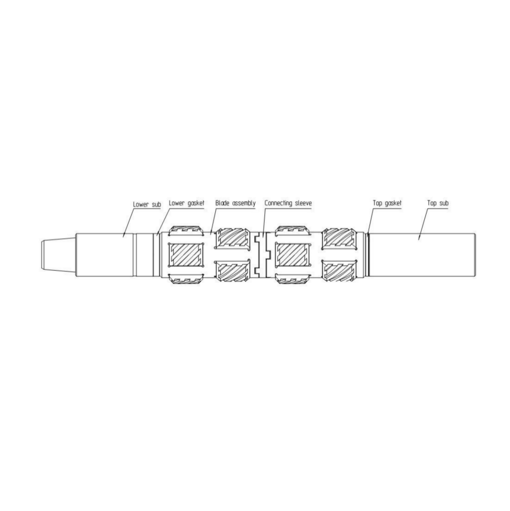
GX-X Type Non-rotating Casing Scraper is one of the indispensable auxiliary tools for well completion, testing and downhole operation. The main purpose of the scraper is to remove cement, sand, residual bullets, scratches, paraffin, burrs and other attachments from the inner wall of the downhole casing, and protect the inner wall of the casing, so as to facilitate the normal operation of all drilling tools. Type B non rotating scraper is not suitable for drilling operation.
Product Introduction:
GX-X Type Non-rotating Casing Scraper is one of the indispensable auxiliary tools for well completion, testing and downhole operation. The main purpose of the scraper is to remove cement, sand, residual bullets, scratches, paraffin, burrs and other attachments from the inner wall of the downhole casing, and protect the inner wall of the casing, so as to facilitate the normal operation of all drilling tools. Type B non rotating scraper is not suitable for drilling operation.
Product Structure:
GX-X Type Non-rotating Casing Scraper (Hereinafter referred to as scraper) is composed of Lower sub, Lower gasket, Blade assembly, Connecting sleeve, Top gasket, Top sub, etc. The center sleeve and the Blade assembly are slide on the lower joint and can rotate freely around the lower joint. Choose different sizes of center sleeve and blade assembly according to the different inner diameter of casing. The structure is shown in the figure.
Construction and Principle:
Before entering the well, the installation size of the scraper blade is larger than the inner diameter of the casing. After entering the well, the scraper blade is forced to press down the spring, and the spring provides the radial tension. When scraping hard material, it can be scraped to the inner diameter of casing after multiple scraping. The scraper is connected to the lower end of the downhole string, and the up and down movement of the string is the axial feed in the scraping process. If it is used to check whether the hole of the casing passed is smooth, do not rotate when the tool passes. If the weight indicator does not show abnormally, it means that the inner wall of the casing is smooth.
Care & Maintenance:
After each use, the scraper should be cleaned, and do not store it for a long time to prevent the blade from rusting.
Check all parts after disassembly. If the spring is damaged or has residual deformation (the free height is significantly
reduced), it must be replaced with a new one.
All main parts shall be inspected by flaw detection. During assembly, apply high-quality grease on each thread and
enough antirust oil on other parts to keep the scraper in good condition for use.
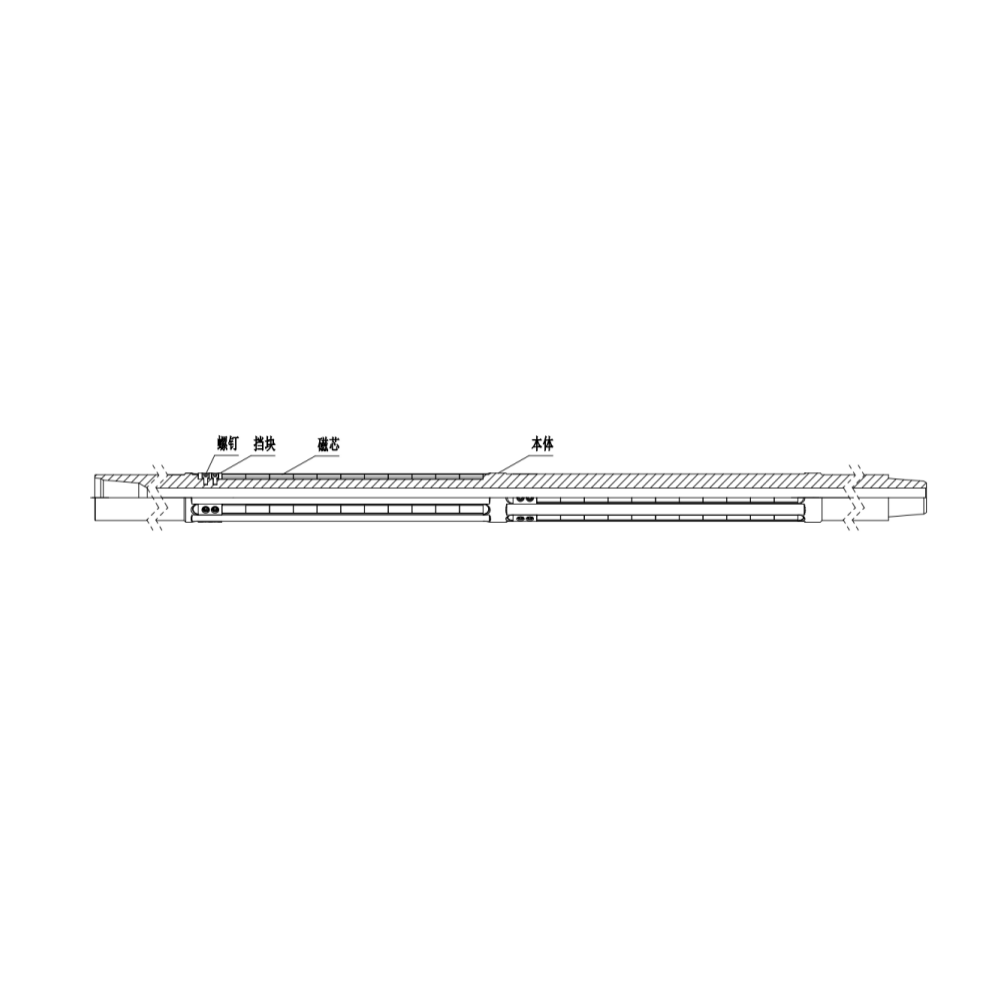
YTQC Type Drill String Fishing Magnet is one of the auxiliary tools to ensure the normal drilling operation and bottom hole cleaning in the process of downhole accident treatment. The main feature of this product is that it works together with the grinding shoes in the fishing operation, which is different from the previous method of lifting the drill after milling, and then connecting the drill string with the strong magnetic fishing tool to go down the well for cleaning bottom hole , saving a trip down the well operation, which not only saves the drilling cost, but also saves the fishing operation time.
Product Introduction:
YTQC Type Drill String Fishing Magnet is one of the auxiliary tools to ensure the normal drilling operation and bottom hole cleaning in the process of downhole accident treatment. The main feature of this product is that it works together with the grinding shoes in the fishing operation, which is different from the previous method of lifting the drill after milling, and then connecting the drill string with the strong magnetic fishing tool to go down the well for cleaning bottom hole , saving a trip down the well operation, which not only saves the drilling cost, but also saves the fishing operation time.
Product Structure:
YTQC Type Drill String Fishing Magnet is composed of body, magnetic core, stop block, screw, etc.
Construction and Principle:
In the milling and fishing operation, through circulating drilling fluid, the bottom hole debris will be adsorbed to the magnetic core of the drill string fishing magnet under the circulation action, and these debris will return to the ground together with the drill string fishing magnet, so as to achieve the function of milling operation and cleaning the bottom hole at any time.
Care & Maintenance:
After each use, the tool should be cleaned, and do not store it for a long time, , in order to avoid corrosion.
Check all parts after disassembly. The magnetic core found to have decreased magnetism must be replaced with a new
one.
All main parts shall be inspected by flaw detection. During assembly, apply high-quality grease on each thread and
enough antirust oil on other parts. At the same time, the magnetic core should be protected with special tool kit to
avoid collision. Keep the tool in good condition for use.
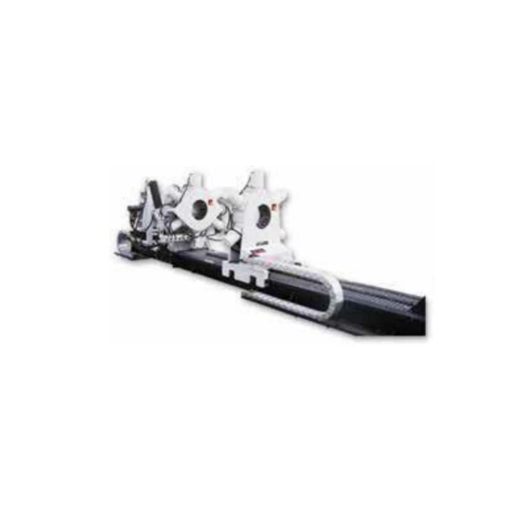
CZJ-400IS Open Type Quick-Rotary Hydraulic Bucking Unit is the Hydraulic Make/Break Unit with an Open Type Hydraulic Spinner (Quick-Rotary) Assembly. Open Type Quick Rotary Spinner enables easy loading and unloading of tools during operation. The ease of operation greatly improves work efficiency, and reduces the risk of tools damage due to collision.
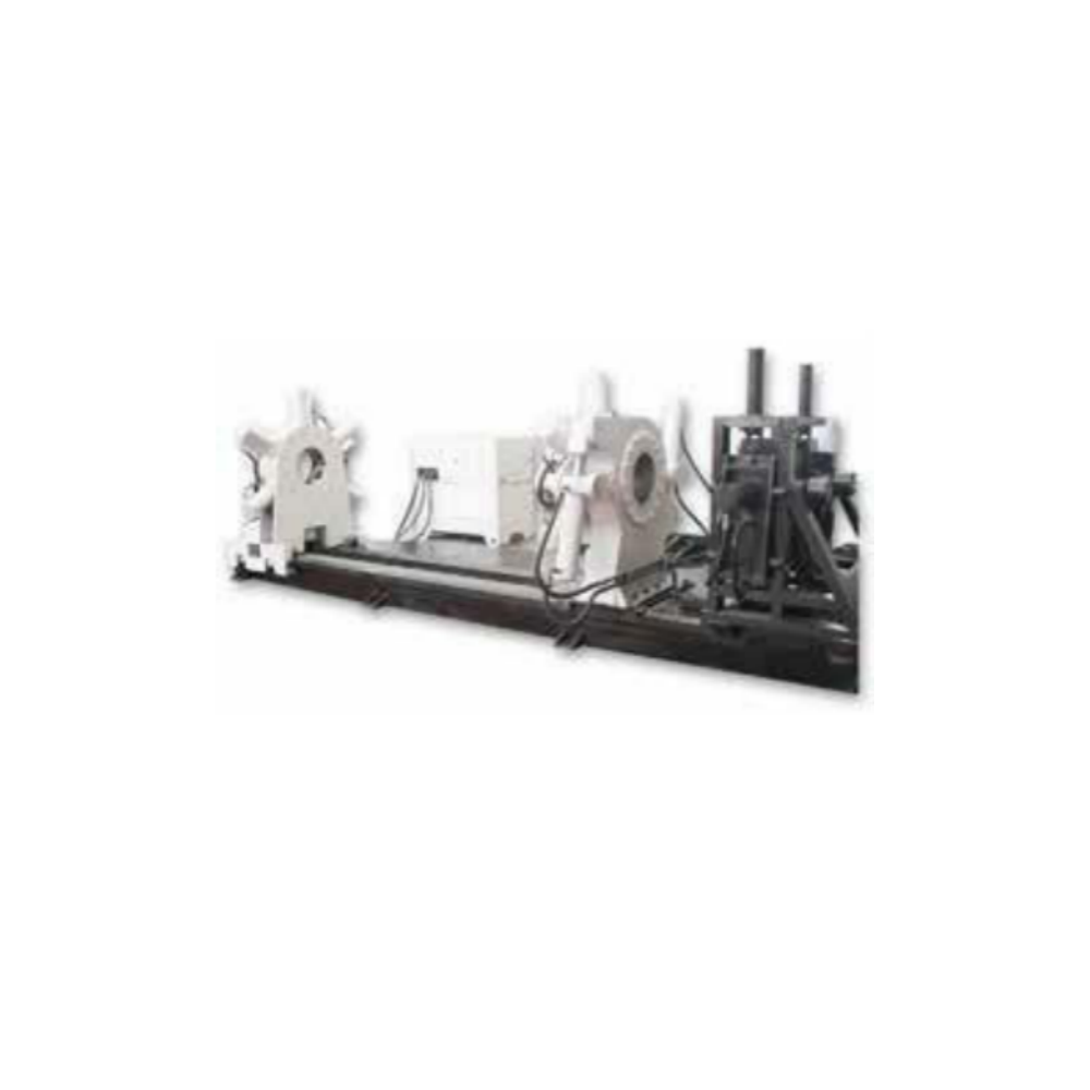
CZJ320W Hydraulic Bucking Unit is specifically designed to cater to the structures and mechanical features of completion tools. It offers the most precise and efficient means of achieving proper make-up/break-out torque either on or off the rig floor for completion tools, drilling tools, oil recovery tools, geological tools and other thin-walled tubes. One of the main advantages of CzJ-320W is the design whereby the clamping force is proportional to the torque provided. Moderate clamp force, small make-up torque and its clamp diameter range makes it suitable for make-up and break-out of completion tools.
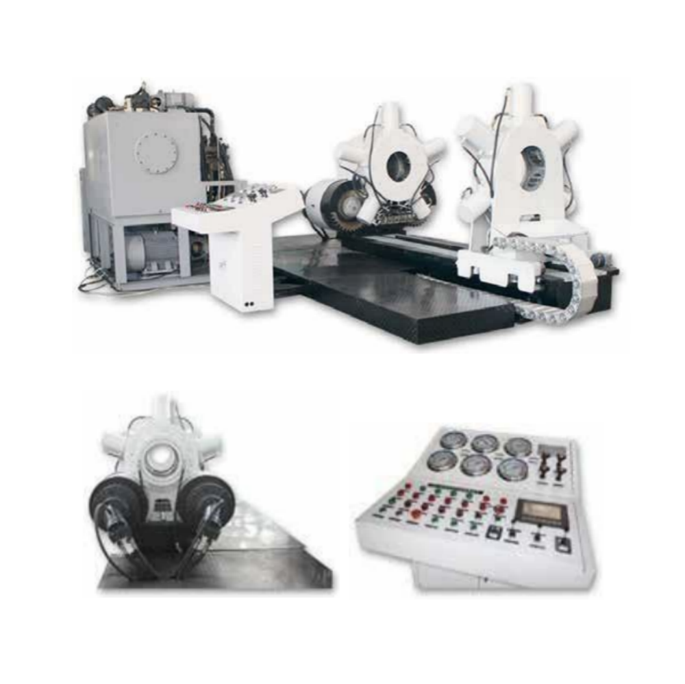
CZJQZ-II 360° Rotation Hydraulic Make/Break unit is designed to safely and efficiently make-up/break-out downhole tools and motors. It adopts a unique 360° rotational headstock clamp design. This unit is designed for fast, accurate and dependable make up and break out of threaded connections. The 360° rotational clamp design greatly enhances the speed and accuracy of make-up and break-out of tools.
FOLLOWING ARE THE ADVANTAGES OF HAVING 360° CONTINUOUS ROTATIONAL HEADSTOCK:
1. Synchronized gripping force:- The headstock and tailstock each contain five radially arranged heavy duty clamping cylinders(imported). It’s designed to ensure a continuous clamping range so as to achieve synchronized gripping force on the tools and precise axial alignment of the tools.
2. Enhanced work efficiency:- The 360° continuous rotational headstock enables the make-up and break-out of tools approximately 18 times faster than normal conventional headstock design which are limited to a 40° rotation per time.
3. Reduces damage on work piece:- With the unique continuous rotational feature, only one clamping action is required to achieve a 360° locking / unlocking of the thread. This greatly reduces the number of times the work piece has to be clamped, thus reducing clamping teeth marks and damage on the surface of the work piece.
4. Precise Torque Application:- Fully imported hydraulic system ensures the accuracy of force applied on each piston cylinder, thus ensuring the precision of torque force on the tools during make-up and break-out.
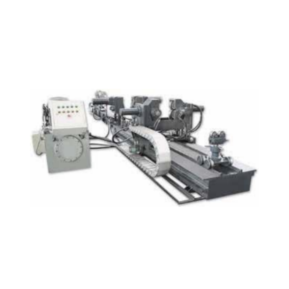
CZPT-II Hydraulic make-up/break-out platform is mainly used with Make/ Break unit assisting in the pre-assembly of drilling tools, whereby special guiding and alignment of tools are required for proper locking and unlocking of threads during assembly. The precision of tool alignment is the key to fast and accurate make-up and break-out of tools either in the workshop or on the rig. CZPT-II is generally designed to support all types of Make-up/Break-out Unit for its pre-assembly tool alignment and thread guiding. CZPT-II ensures high production efficiency during make- up/break-out of tools.

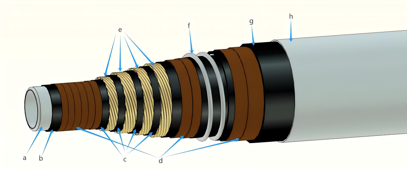


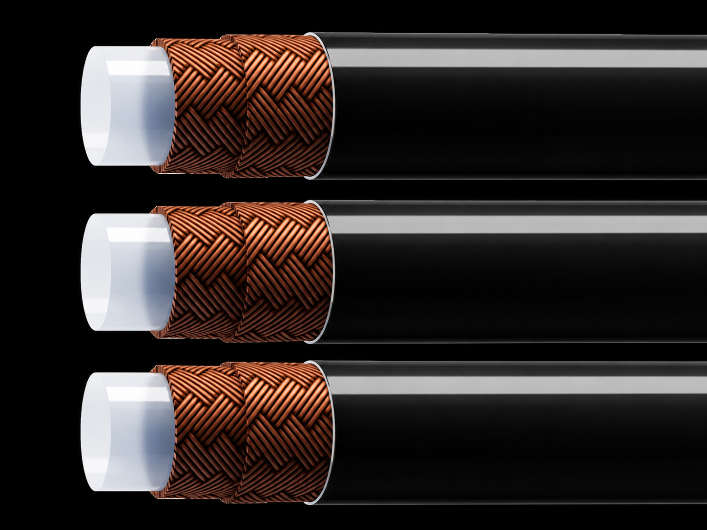
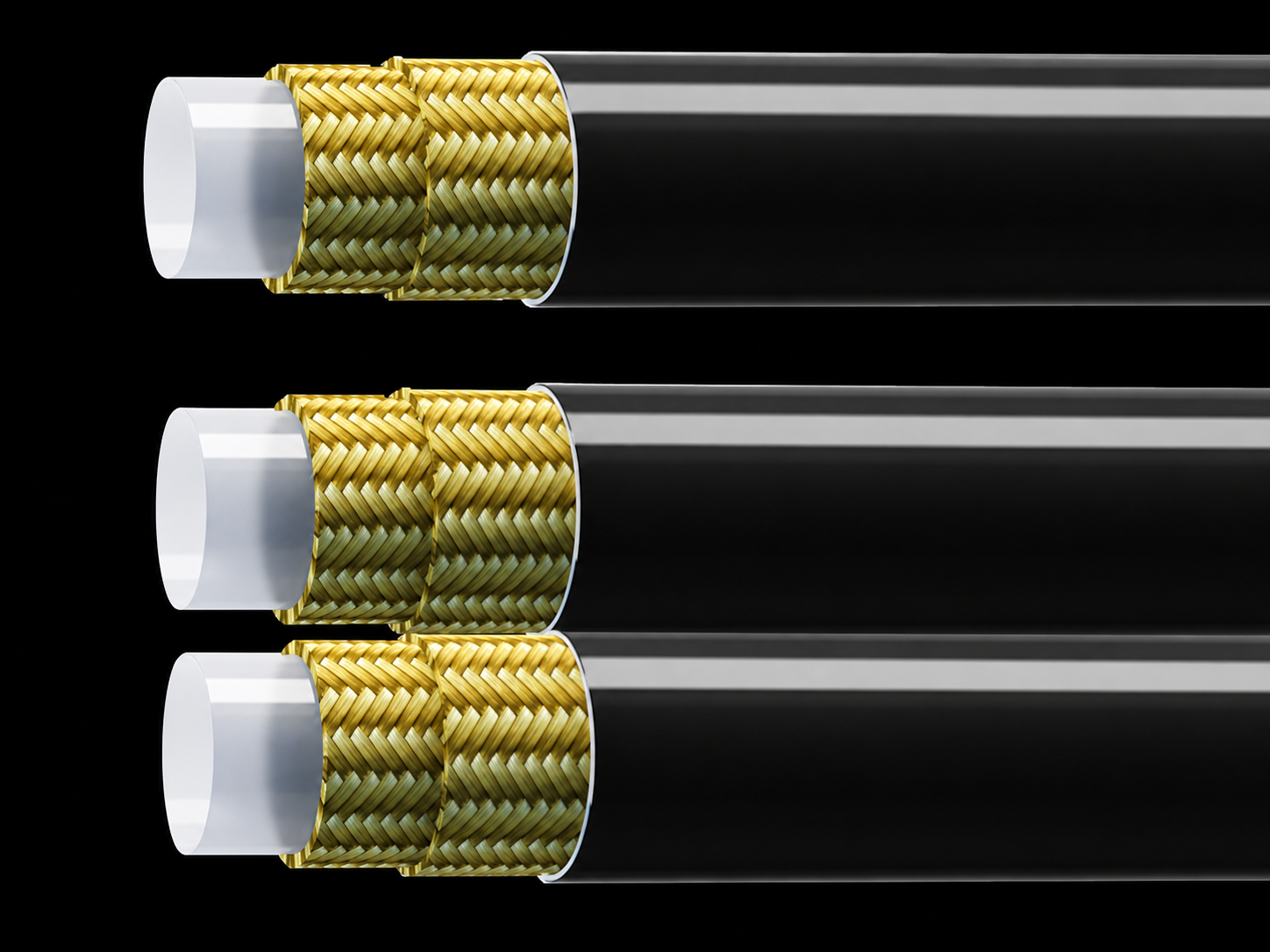
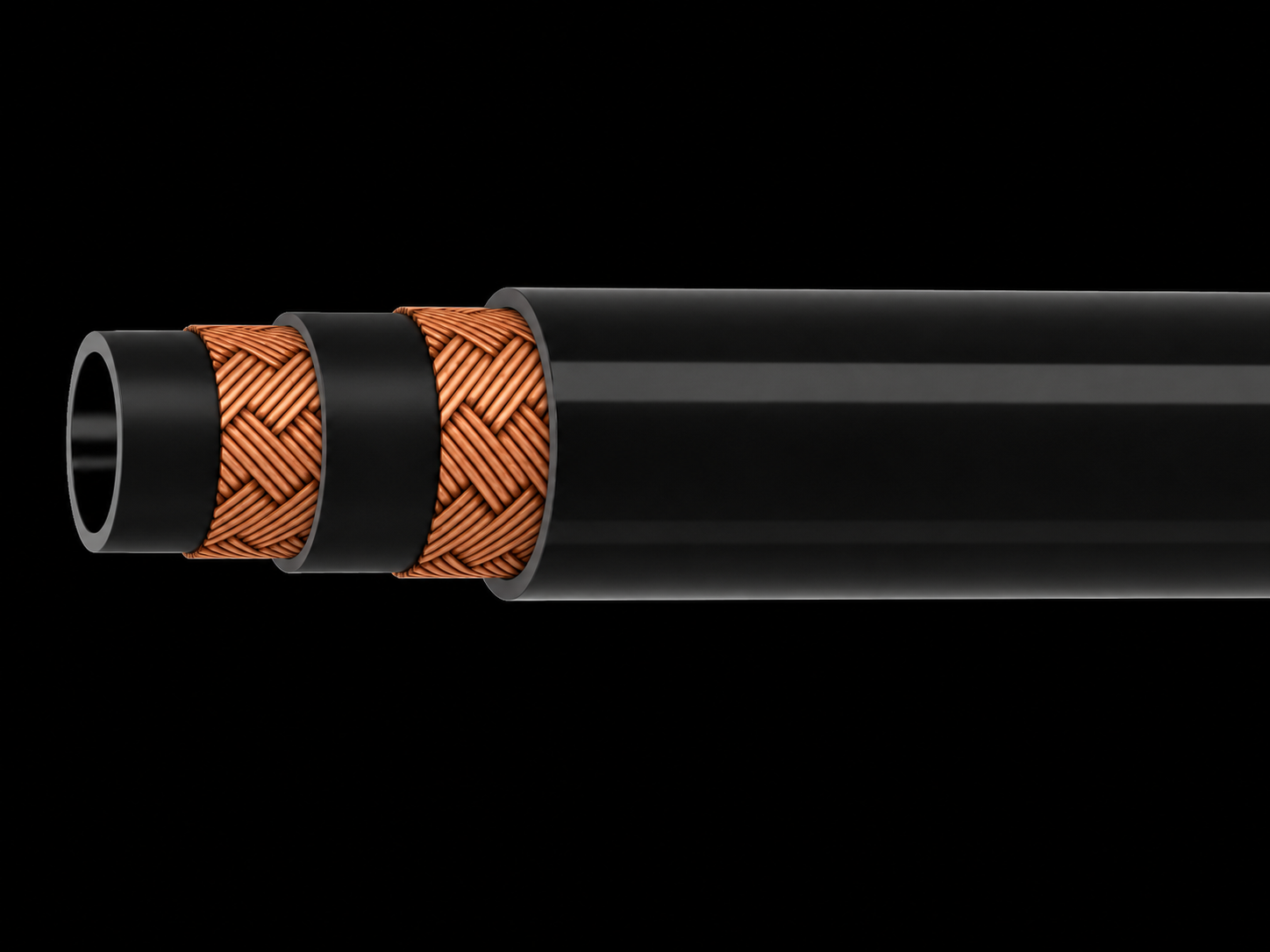
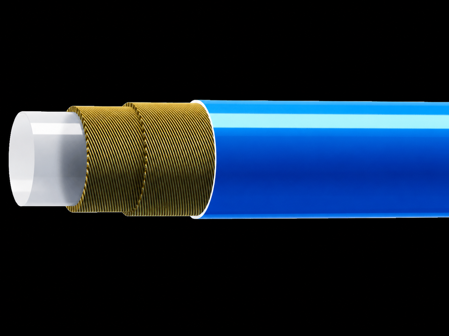
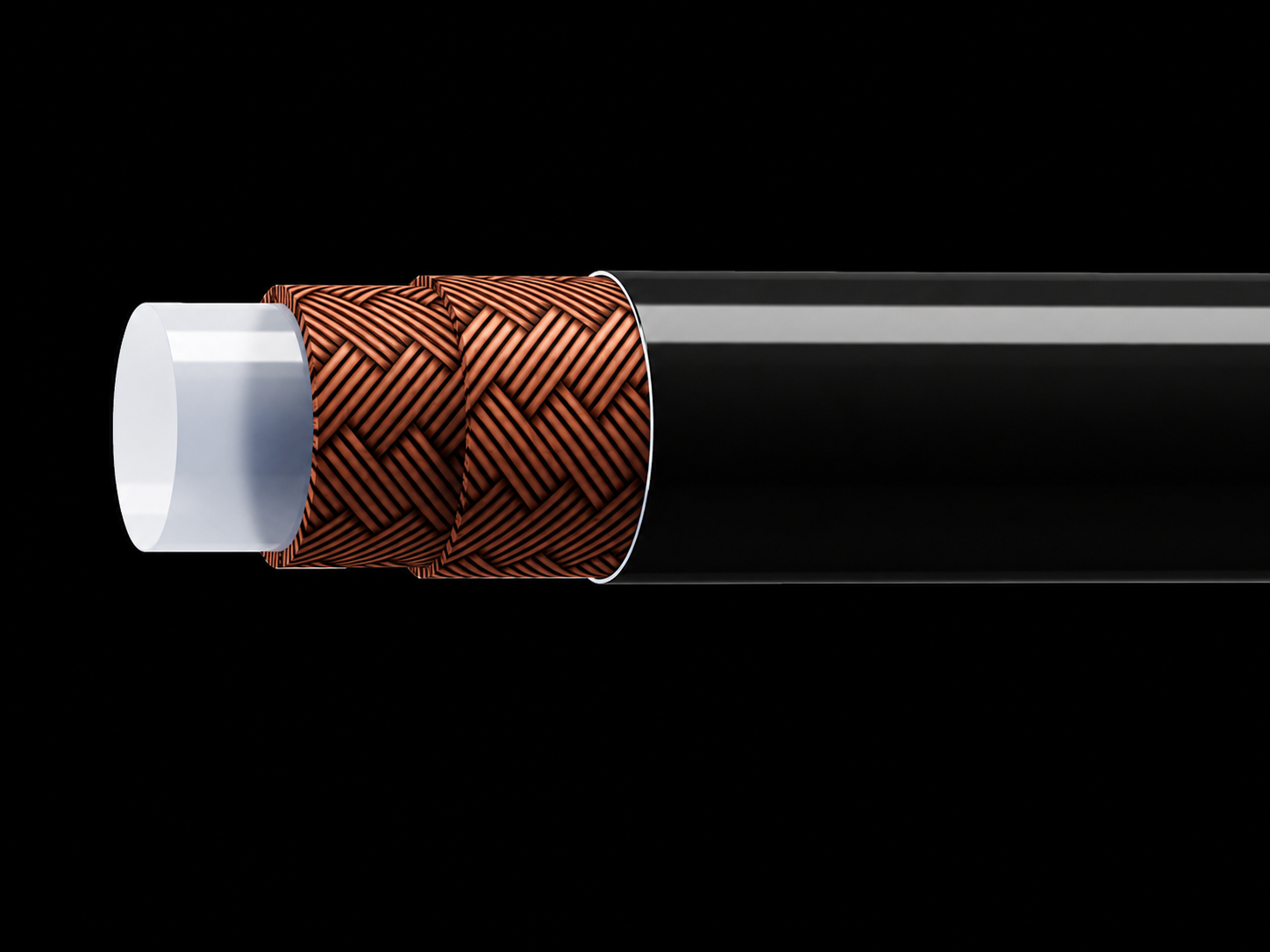


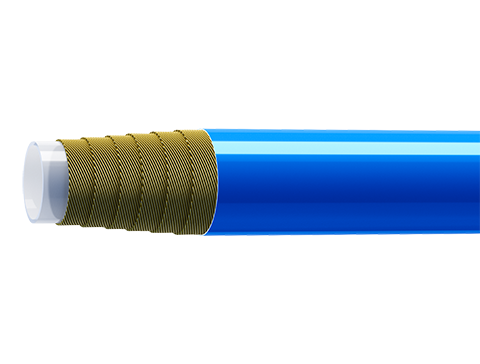
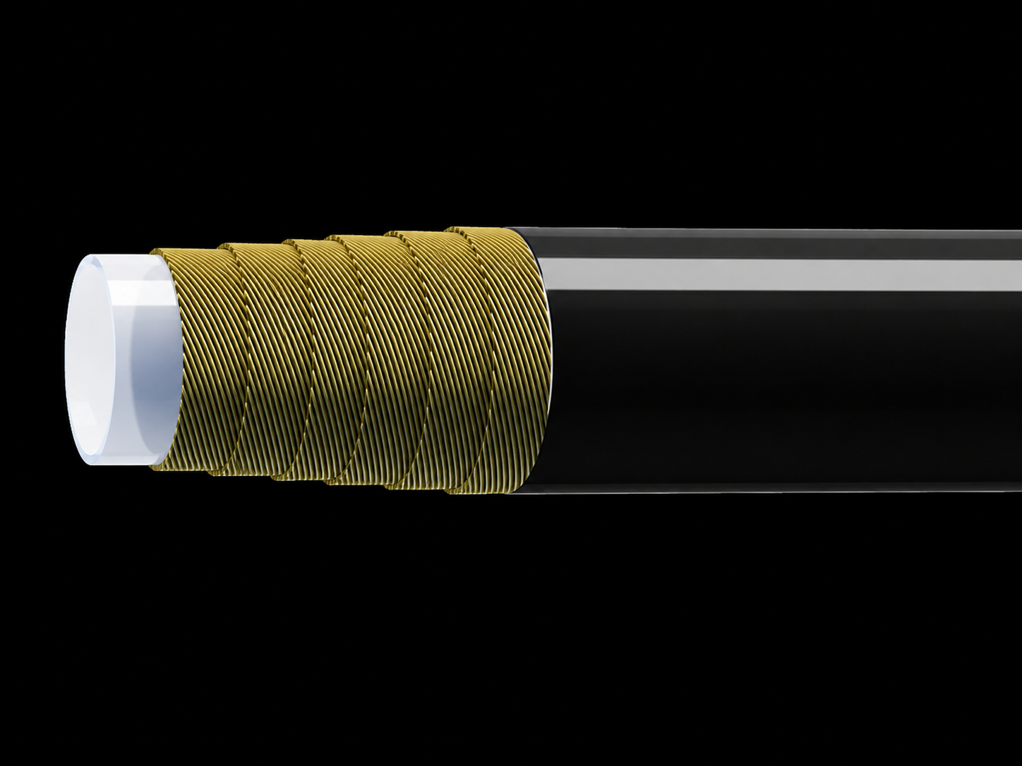

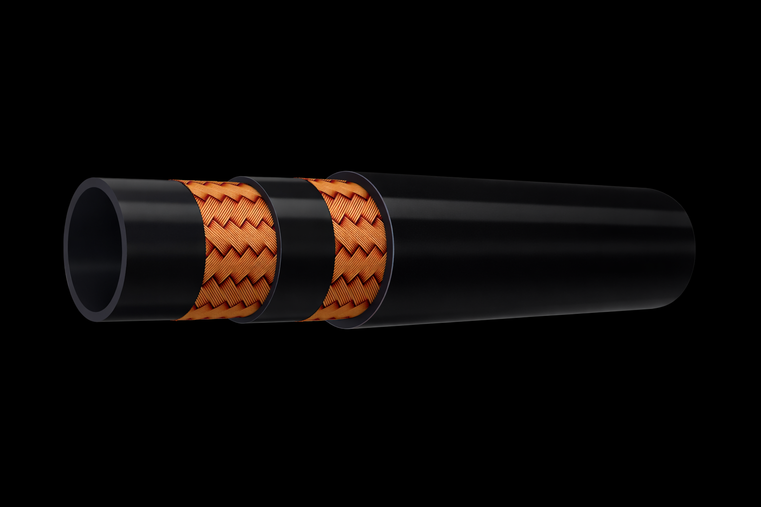


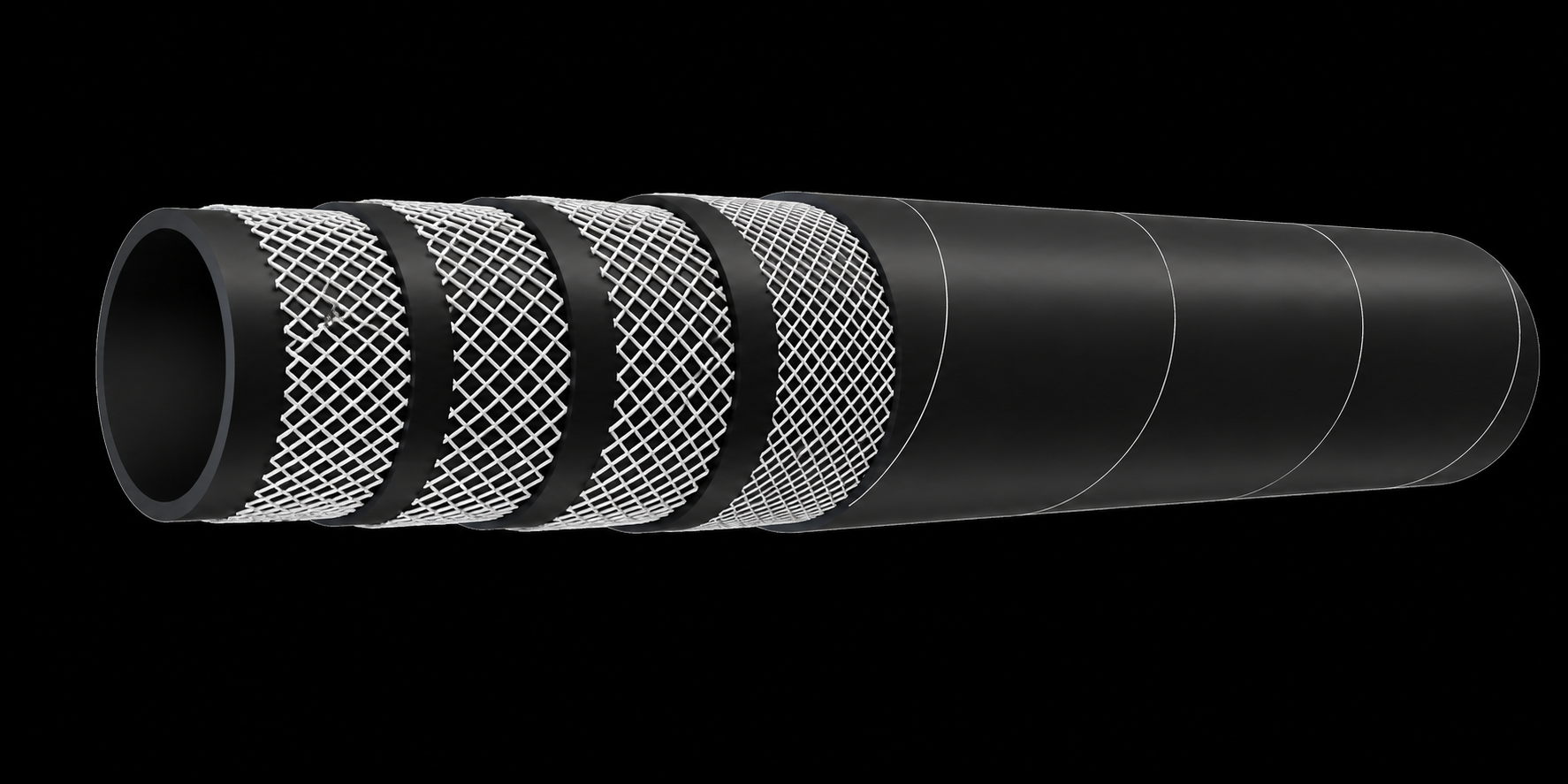

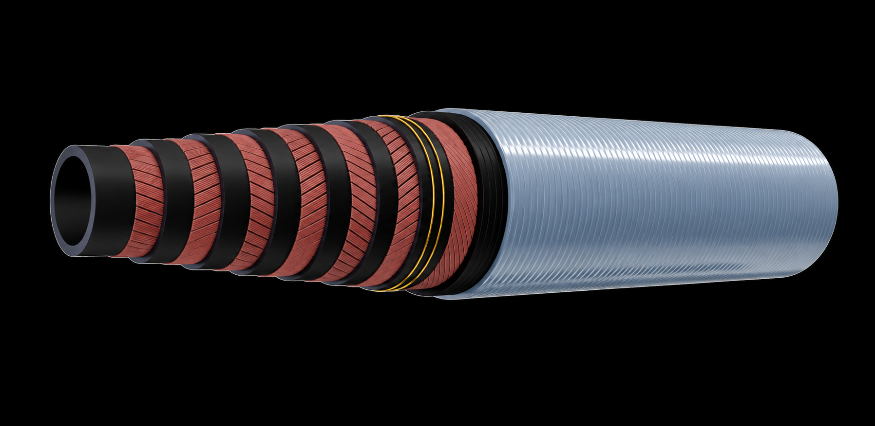
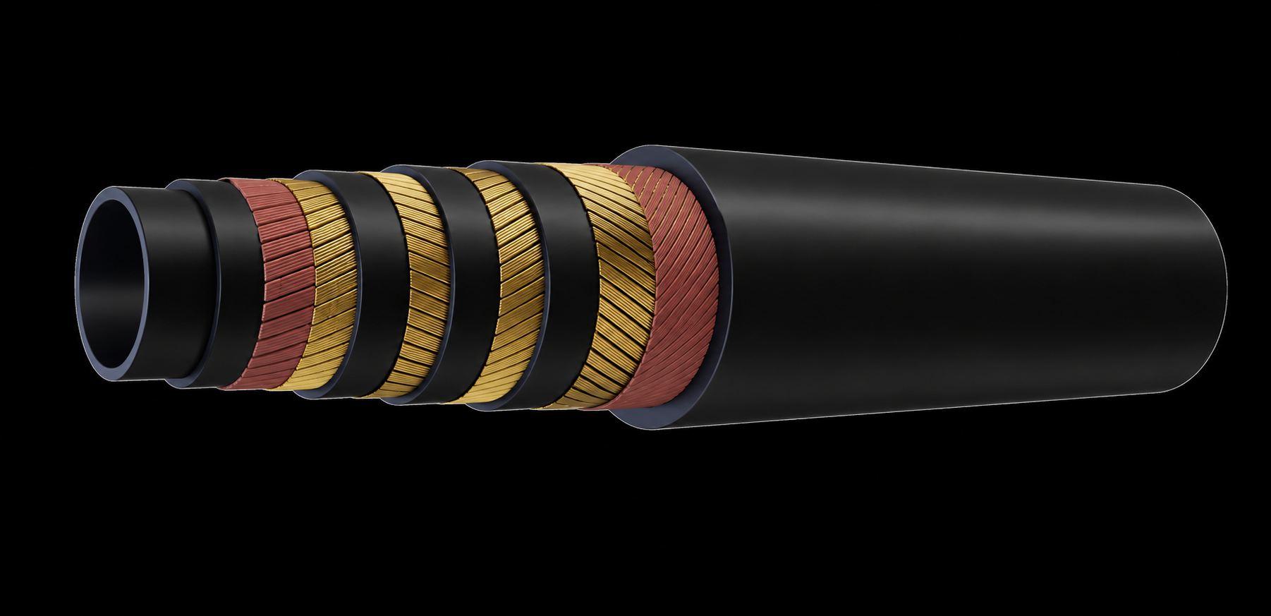
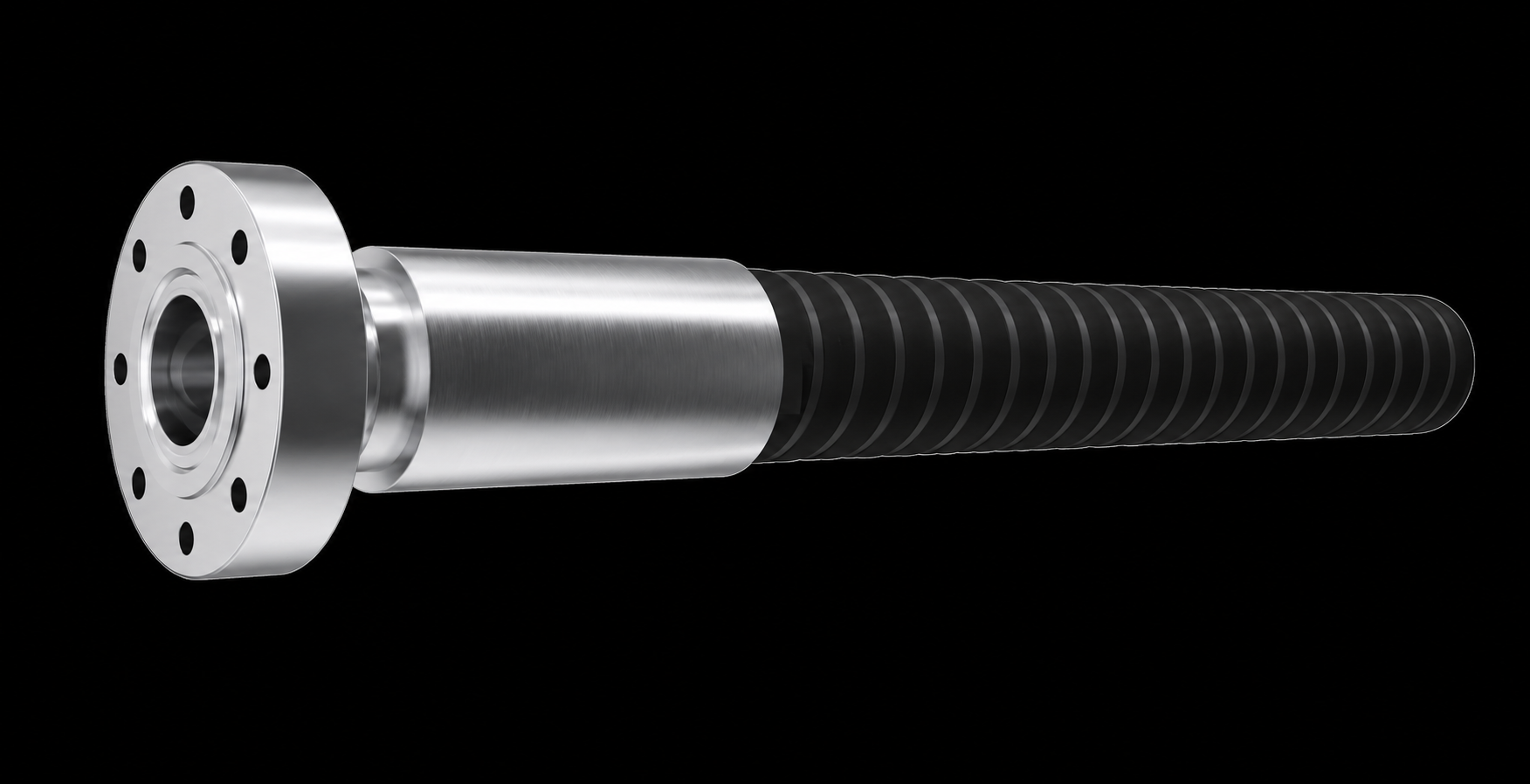


_1762946448.webp)


Introduction:Chloroprene Rubber CR (Chloroprene Rubber) has high tensile strength, elongation and other physical mechanical properties, and has good oil resistance, heat aging resistance, flame retardant, light resistance, ozone resistance, acid and alkali resistance , Chemical resistance and other chemical properties. Therefore, it is widely used in the manufacture of hoses, tapes, wire and cable sheaths, rubber rollers, rubber plates, adhesives and various sealed shock-absorbing products
Tips:Neoprene rubber compound, full-color hardness range customized, hardness 20-95 degrees. The formula can be prepared according to the specific requirements of customer products
Introduction:Natural Rubber (Natural Rubber) has excellent resilience, abrasion resistance, tear resistance, high tensile strength and other physical and mechanical properties, as well as good electrical insulation, water barrier, air tightness, resistance Electrochemical properties such as acidity and alkalinity. Therefore, natural rubber is often used in rubber tires, hoses, tapes, and various shock-absorbing and sealing products
Tip:According to customer needs, can customize natural rubber compound with full color and hardness range of 20-95 degrees

Application:Widely used in the automotive and oil field industries, used to manufacture hoses, rubber plates and sealed shock-absorbing products, especially oil-resistant rubber products that require high temperature resistance, aging resistance and corrosion resistance
Introduction:Hydrogenated Nitrile Rubber HNBR (Hydrogenated Nitrile Rubber) is a highly saturated elastomer obtained by special hydrogenation of nitrile rubber. Hydrogenated nitrile rubber has good oil resistance (good resistance to fuel oil, lubricating oil, aromatic solvents); and due to its highly saturated structure, it has good heat resistance and excellent chemical resistance (for Freon, acid and alkali have good resistance), excellent ozone resistance, high resistance to compression permanent deformation; at the same time hydrogenated nitrile rubber also has high strength, high tear performance, excellent wear resistance, etc. It is a rubber with excellent overall performance

Introduction:Polymerized Styrene Butadiene Rubber (Polymerized Styrene Butadiene Rubber) has physical and mechanical properties, processing properties and product performance close to that of natural rubber. Some properties such as wear resistance, heat resistance, aging resistance and vulcanization return are better than natural rubber , Can be used in combination with natural rubber and various synthetic rubbers, widely used in the production of tires, tapes, hoses, wires and cables, medical appliances and various rubber products. One of the rubber varieties produced
Tip:According to customer, can customize styrene-butadiene rubber compound with full color and hardness range of 20-95 degrees
Introduction:Ethylene Propylene Diene Monomer has excellent ozone resistance, weather resistance, heat aging resistance, good chemical corrosion resistance, electrical insulation performance, hot water and steam resistance, and low temperature resistance. Therefore, EPDM is mainly used in automotive parts (scrapers, seals, dustproof rubber sleeves and other sealed shock-absorbing products), chemical-resistant hoses, rubber rollers, gaskets, etc., as well as high, medium and low voltage insulation Rubber material
Tip:According to customer, can customize EPDM rubber compound with full color and hardness range of 20-95 degrees
Introduction:NBR (Nitrile Butadiene Rubber) has excellent oil resistance, air tightness, good water resistance, acid and alkali resistance, good wear resistance and aging resistance. The performance of nitrile rubber varies slightly according to the distribution of its molecular segments. Therefore, nitrile rubber is widely used in oil-resistant rubber products, such as hoses, rubber rollers, seals and shock-absorbing products
Tip:According to customer, can customize full-color nitrile rubber compound with a hardness range of 20-95 degrees
Pad material: NBR、HNBR、EPDM、HEPDM、VITON
Features: Anti-aging, corrosion resistance, long life
Special Note: Different types of heat exchanger gaskets can be customized according to drawings, sample pads or plates
Features :The product is made of pure natural rubber and several other types of rubber. It has the characteristics of good elasticity and strong pressure resistance. In the processing method, the patented steel wire winding production method is adopted to make the product reach the limit in the use of pressure and durability. , the working pressure is more than 40KG
temperature range:Operating temperature 0-80℃
Production process: This product is made of advanced EPDM rubber production technology that our company has inherited for many years and has been continuously improved and perfected. The raw materials are 100% pure EPDM raw rubber imported from the United States. The surface glue of the thread glue is all EPDM rubber, which truly achieves "the appearance is the same"
Features: It is characterized by high temperature resistance, acid resistance and alkali resistance. It is a product with strong comprehensive performance
Application:It can be widely used in the fields of food, medicine and high temperature products
Temperature range:-20°C-160°C
Features:This product is made of green, environmentally friendly and non-toxic food-grade rubber—silicone rubber, which has the properties of anti-corrosion, low temperature resistance and high temperature resistance

Application:Suitable for oil or liquid with high oil content
Temperature range:0-130°C
Features:This product has excellent oil resistance, high wear resistance and heat resistance, and can be used for a long time in the air at 120°C or in oil at 150°C
Application:Suitable for high standard or mixed liquid
Temperature range:10-150°C
Features:The product has good physical and mechanical properties, oil resistance, heat resistance, flame resistance, aging resistance, acid and alkali resistance
| Model | LT60B,LT60H |
| Plate thickness | 0.5/0.6mm |
| Size of corner holes of plate | 50mm |
| Maximum processing capacity | 36m³/h |
| Connection diameter | DN50 |
| Working pressure | 1.0/1.6MPa |
| Test pressure | 1.3/2.1MPa |
| Model | LT30 |
| Plate thickness | 0.5/0.6mm |
| Size of corner holes of plate | 32mm |
| Maximum processing capacity | 15m³/h |
| Connection diameter | DN32 |
| Working pressure | 1.0/1.6MPa |
| Test pressure | 1.3/2.1MPa |
| Model | LTS60 |
| Plate thickness | 0.5/0.6mm |
| Size of corner holes of plate | 65mm |
| Maximum processing capacity | 45m³/h |
| Connection diameter | DN65 |
| Working pressure | 1.0/1.6MPa |
| Test pressure | 1.3/2.1MPa |
| Model | LT60L |
| Plate thickness | 0.5/0.6mm |
| Size of corner holes of plate | 50mm |
| Maximum processing capacity | 36m³/h |
| Connection diameter | DN50 |
| Working pressure | 1.0/1.6MPa |
| Test pressure | 1.3/2.1MPa |
| Model | LT100B,LT100H |
| Plate thickness | 0.5/0.6mm |
| Size of corner holes of plate | 100mm |
| Maximum processing capacity | 140m³/h |
| Connection diameter | DN100 |
| Working pressure | 1.0/1.6MPa |
| Test pressure | 1.3/2.1MPa |
| Model | LT100D |
| Plate thickness | 0.5/0.6mm |
| Size of corner holes of plate | 100mm |
| Maximum processing capacity | 140m³/h |
| Connection diameter | DN100 |
| Working pressure | 1.0/1.6MPa |
| Test pressure | 1.3/2.1MPa |
| Model | LT100L |
| Plate thickness | 0.5/0.6mm |
| Size of corner holes of plate | 100mm |
| Maximum processing capacity | 140m³/h |
| Connection diameter | DN100 |
| Working pressure | 1.0/1.6MPa |
| Test pressure | 1.3/2.1MPa |
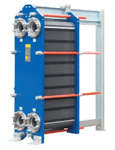
| Model | LT150B,LT150H |
| Plate thickness | 0.5/0.6mm |
| Size of corner holes of plate | 150mm |
| Maximum processing capacity | 360m³/h |
| Connection diameter | DN150 |
| Working pressure | 1.0/1.6MPa |
| Test pressure | 1.3/2.1MPa |

| Model | LT200B, LT200H |
| Plate thickness | 0.5/0.6mm |
| Plate Angle hole size | 200mm |
| Max throughput | 600m³/h |
| Pipe diameter | DN200 |
| Working pressure | 1.0/1.6MPa |
| Test pressure | 1.3/2.1MPa |
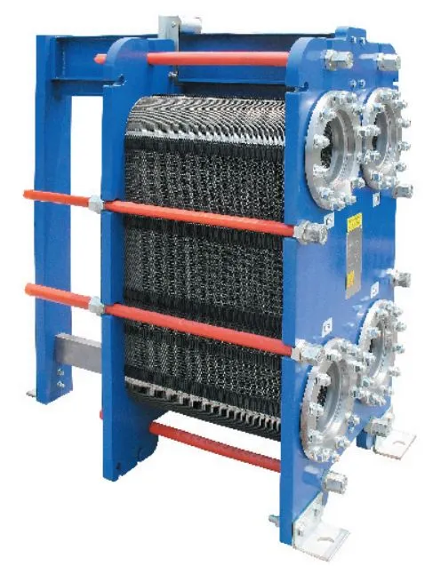
| model | LTS200 |
| Thi ckne ss | 0.5/0.6mm |
| Plate Angle hole size | 200mm |
| maximum throughput | 600m³/h |
| Connection diameter | DN200 |
| working pressure | 1.0/1.6MPa |
| test pressure | 1.3/2.1MPa |
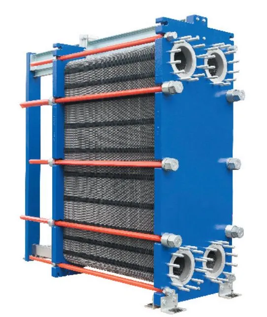
| model | LT250B,LT250H |
| Plate thickness | 0.5/0.6mm |
| Plate Angle hole size | 250mm |
| maximum throughput | 900m³/h |
| Nozzle diameter | DN250 |
| working pressure | 1.0/1.6MPa |
| test pressure | 1.3/2.1MPa |
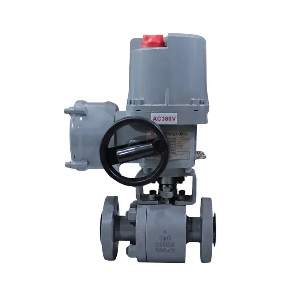
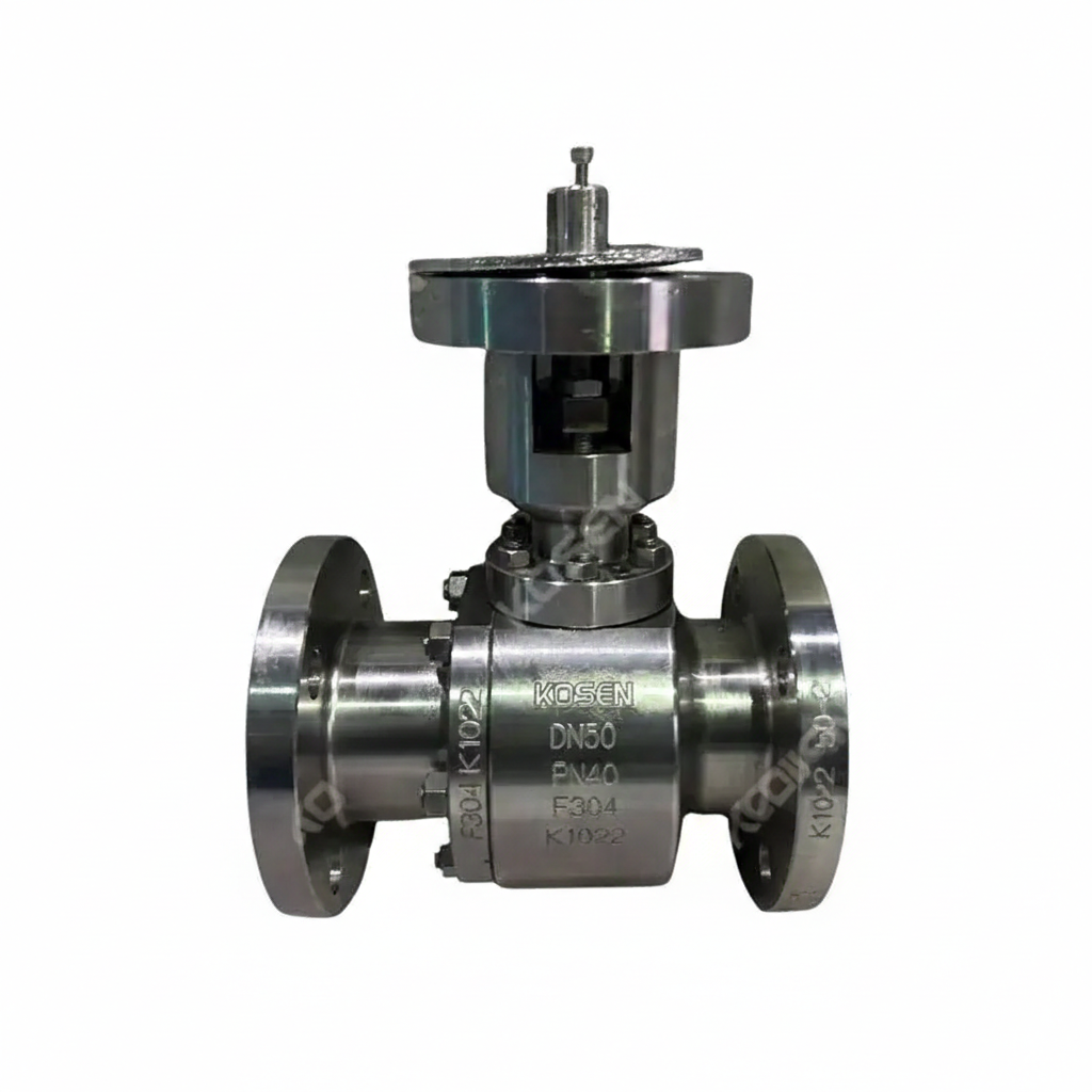
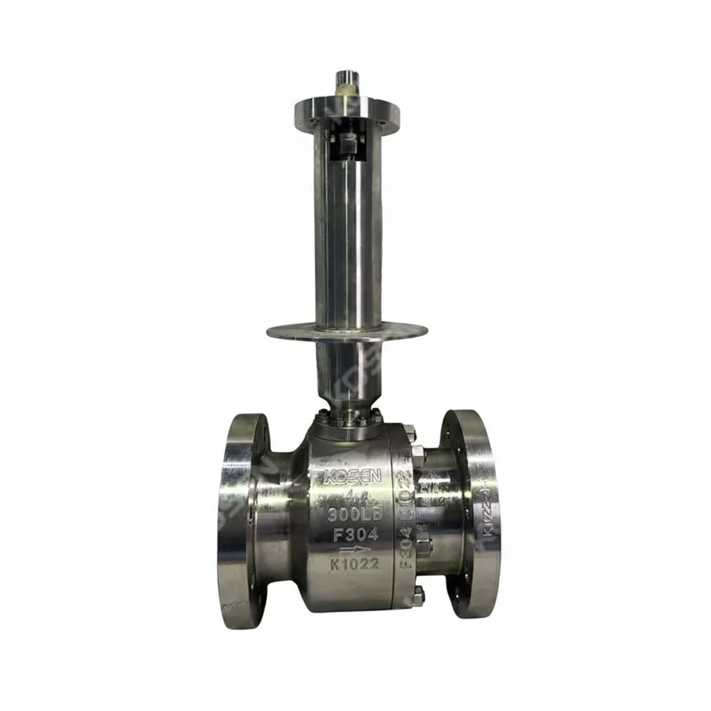
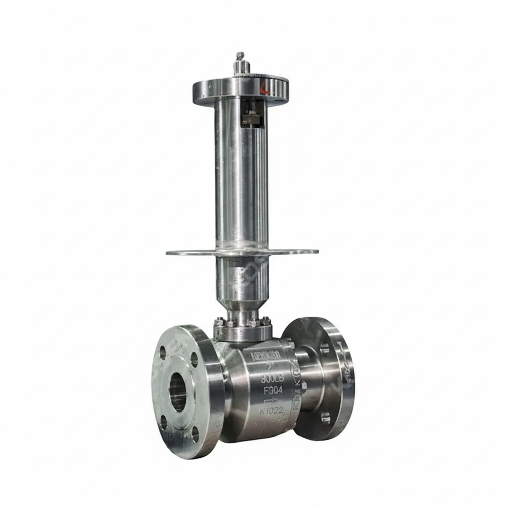
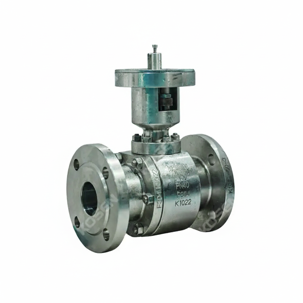
The Stainless Steel Ball Valve Supplier offers a high-quality 80 mm floating ball valve, designed with ASTM A351 CF8 stainless steel for superior durability and corrosion resistance. This 3-inch (DN80) valve is rated for Class 150 LB and PN20 pressure classes, featuring lever operation for easy control. It comes with raised face (RF) flanged ends, ensuring secure and reliable connections in various industrial applications.
Model No.: KV-20251206-FBV-01
Hits: 4
The ASTM B148 C95800 Floating Ball Valve is a high-quality, reduced bore valve designed for industrial applications. It features an aluminum bronze body, ensuring durability and corrosion resistance. With a size of 6 x 4 inches (DN150 x DN100), it offers a reduced bore for efficient flow control. Certified to API 6D standards, this valve is rated at 150 LB and PN20, making it suitable for a wide range of pressure applications. Its RF (Raised Face) ends facilitate secure and reliable connections.
Model No.: KV-20250609-FBV-01
Hits: 31
The ASTM A182 F304 Ball Valve Factory offers a high-quality floating ball valve designed for superior performance and durability. This valve features a 2-piece forged stainless steel body made from ASTM A182 F304 material, ensuring excellent corrosion resistance and strength. It has a nominal diameter of DN25 (1 inch) and a pressure rating of PN16 (Class 150 LB), making it suitable for a wide range of applications. The valve is equipped with RF (Raised Face) flanged ends for secure and reliable connections and is operated by a lever for easy control.
Model No.: KV-20250607-FBV-02
Hits: 25
The Carbon Steel Floating Ball Valve Plant offers a robust and reliable solution for various industrial applications. This valve features a 2-piece valve body constructed from ASTM A216 WCB carbon steel, ensuring durability and strength. It adheres to API 6D standards and is designed with a 2-inch (DN50) diameter and a pressure rating of 300 LB (PN50). The valve is equipped with RF (Raised Face) flanged ends for secure connections and is operated via a lever, providing easy control.
Model No.: KV-20250607-FBV-01
Hits: 39
The Aluminum Bronze Floating Ball Valve from the factory is a robust industrial valve designed for demanding applications. It adheres to API 6D standards and features an ASTM B148 C95800 aluminum bronze body, offering excellent corrosion resistance and durability. With a nominal diameter of DN200 (8 inches) and a pressure rating of PN40 (Class 300 LB), it is suitable for high-pressure systems. The valve has RF (raised face) flanged ends for secure connections and includes a gearbox for smooth and reliable operation.
Model No.: KV-20250605-FBV-02
Hits: 7
The ASTM A182 F304 Ball Valve is a high-performance valve designed for industrial applications. It features a floating ball design and is made from forged stainless steel, ensuring durability and corrosion resistance. This valve complies with API 6D standards, offering reliability and safety. With a size of 1 inch (DN25) and a pressure rating of Class 150 LB (PN20), it is suitable for various medium-pressure systems. The wafer ends provide convenient installation, and the lever operation ensures easy control.
Model No.: KV-20250605-FBV-01
Hits: 27
The Full Bore Floating Ball Valve from our factory is a high-performance 2-piece ball valve, compliant with API 6D standards and available in customized sizes to meet specific requirements. It features a full bore design for optimal flow efficiency and is rated at Pressure Class 150 LB and PN20, ensuring durability and reliability. The valve is lever operated for easy control and has RF flanged ends for secure and convenient installation.
Model No.: KV-20250528-FBV-02
Hits: 31
The ASTM A105N Floating Ball Valve is a high-quality 2PC forged ball valve designed for robust performance. It features a full bore, ensuring maximum flow capacity, and is constructed from durable carbon steel, making it suitable for a wide range of applications. The valve is rated at Class 150 LB and PN20, with RF flanged ends for secure and reliable connections. It is lever operated, providing easy and efficient control. This valve is ideal for industries requiring reliable shut-off and flow control in various fluid systems.
Model No.: KV-20250528-FBV-01
Hits: 23
The API 6D Floating Ball Valves Factory produces high-performance ball valves made from forged stainless steel (ASTM A182 F316L). These valves feature a 1-inch (DN25) diameter and are rated at Class 600 LB, ensuring robustness and reliability. They are designed with raised face (RF) flanged ends for secure connections and are operated using a lever, providing easy control. Suitable for demanding industrial applications, these valves meet API 6D standards, ensuring quality and safety.
Model No.: KV-20250526-FBV-02
Hits: 15
The ASTM A216 WCB Ball Valves Plant offers a high-quality floating type ball valve designed for reliable flow control. This 2-piece valve features a carbon steel body (A216 WCB) and conforms to API 6D standards. It has a 2-inch (DN50) diameter, rated at Class 150 LB and PN20 pressure classes, with raised face (RF) flanged ends for secure connections. This valve is ideal for applications requiring durability and performance in various industrial settings.
Model No.: KV-20250526-FBV-01
Hits: 45
The One-piece Single Body Ball Valve is a high-quality floating ball valve designed to meet API 6D standards. It features a robust carbon steel ASTM A216 WCB body, ensuring durability and reliability in demanding industrial applications. The valve has a DN100 (4-inch) size with a pressure rating of PN16 (Class 150 LB), making it suitable for various fluid control needs. Equipped with a lever for easy operation and RF (raised face) ends for secure connections, this valve offers precise control and long-lasting performance.
Model No.: KV-20250515-FBV-01
Hits: 36
_1768811468.webp)
The One Piece Floating Ball Valve is a compact and robust solution for industrial applications. It features a uni-body design made from high-grade stainless steel (SS 316L) conforming to ASTM A351 CF3M standards, ensuring excellent corrosion resistance and durability. With a 1/2-inch size and a pressure rating of 300 LB, it is suitable for systems requiring high performance in smaller dimensions. The valve adheres to API 6D standards, guaranteeing reliability and safety. It has RF (raised face) flanged ends for secure and leak-free connections.
Model No.: KV-20250513-FBV-02
Hits: 15
The ASTM A105 Floating Ball Valve is a high-quality industrial valve designed for demanding applications. It features a 2-piece forged carbon steel body, ensuring durability and strength. The valve complies with API 6D standards, offering reliability and safety. With a 3-inch (DN80) size and a pressure rating of 600 LB (PN100), it is suitable for high-pressure systems. The valve has RF (raised face) flanged ends for secure connections and includes a gearbox for easy operation.
Model No.: KV-20250513-FBV-01
Hits: 21
The Gearbox Floating Ball Valve Factory produces high-quality valves conforming to API 6D standards. These valves feature a Carbon Steel ASTM A216 WCB body, ensuring durability and strength. They have a DN150 (6 Inch) size with a PN40 (Pressure Class 300 LB) rating, making them suitable for high-pressure applications. The valves are equipped with Groove Flanged Ends for reliable connections.
Model No.: KV-20250510-FBV-02
Hits: 28
The Extended Stem Ball Valve Plant provides a Cryogenic Floating Ball Valve that meets BS 5351, API 6D, and ASTM A182 F304 standards. It features a DN50 (2 Inch) size and PN40 (Class 300 LB) pressure rating. The valve is lever operated and has RF ends for secure connections. Its extended stem design enhances accessibility and maintenance.
Model No.: KV-20250510-FBV-01
Hits: 11
The Aluminum Bronze Floating Ball Valve is a high-performance valve designed for seawater, offshore, and marine applications. Constructed from ASTM B148 C95800 aluminum bronze, it offers exceptional corrosion resistance and durability in harsh environments. This reduced port, 4 * 3 inch valve complies with API 6D standards and operates at a Class 150 LB pressure rating. Ideal for fluid control in critical systems, it ensures reliable performance in marine and offshore installations.
Model No.: KV-20250506-FBV-01
Hits: 27
The ASTM A182 F304 Floating Ball Valve, manufactured in compliance with API 6D standards, features a 2-piece forged stainless steel body for superior strength and durability. With a 1/2-inch (DN15) size and a pressure rating of Class 300 LB (PN50), this valve is designed for high-performance fluid control in demanding applications. It comes with RF flanged ends for secure connections and is equipped with a lever for easy manual operation.
Model No.: KV-20250222-FBV-01
Hits: 20
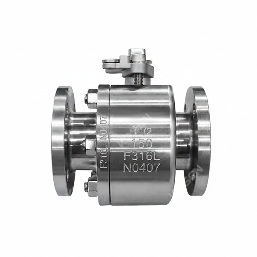
The ASTM A182 F316L Floating Ball Valve Plant produces high-quality ball valves with forged stainless steel bodies, ensuring durability and corrosion resistance. These valves feature a two-piece body design and comply with API 6D standards. Available in 1-1/2 inch (DN40) size, they are rated for Class 150 LB and PN20 pressure classes. The valves are lever-operated and come with raised face (RF) ends, making them suitable for reliable flow control in various industrial applications.
Model No.: KV-20250220-FBV-01
Hits: 35
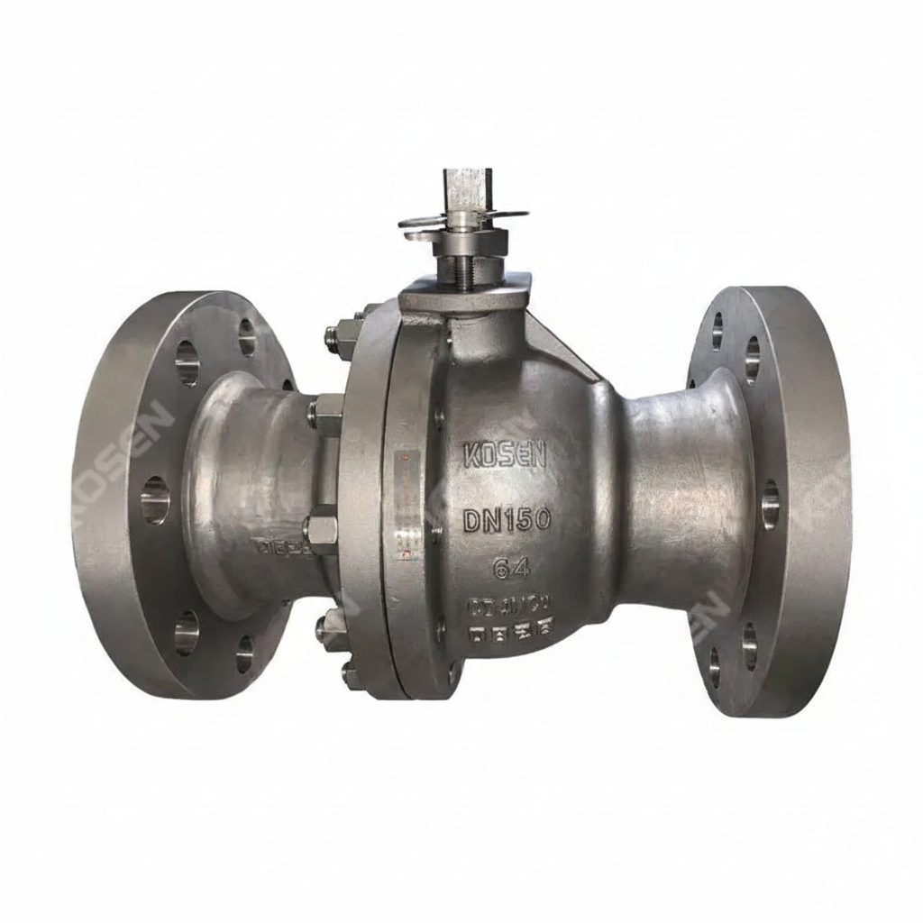
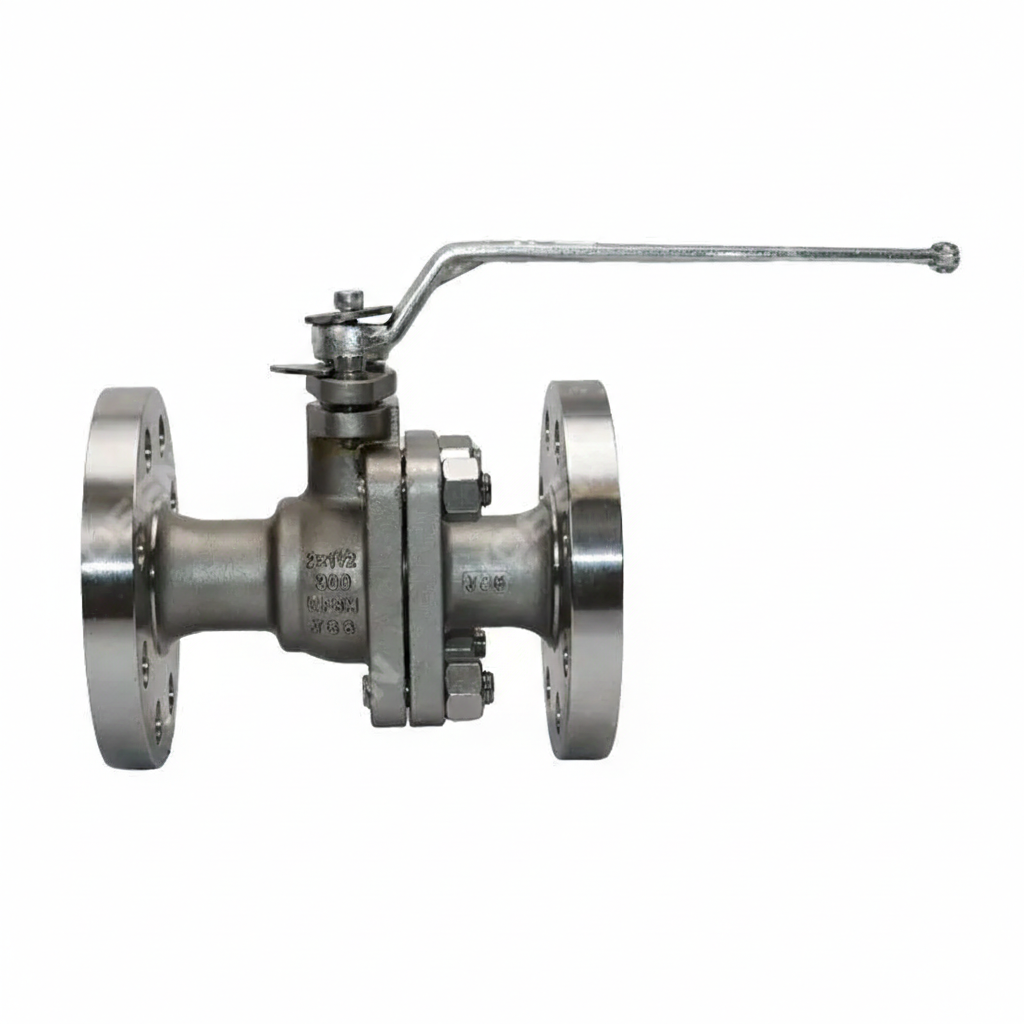
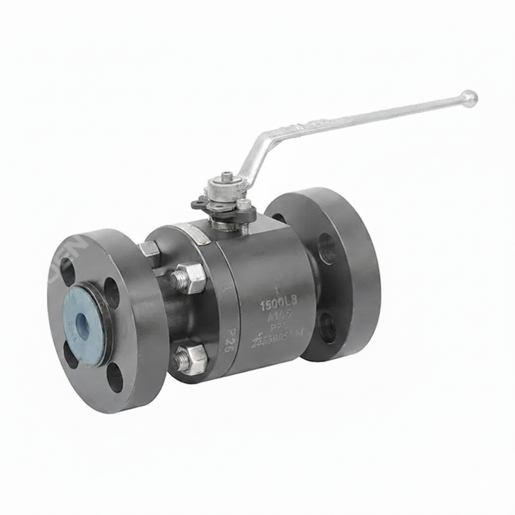
The Spring Return Floating Ball Valve Factory offers a high-performance API 6D compliant valve. Constructed from cast stainless steel (ASTM A351 CF8M), this 4-inch (DN100) valve features a pressure class of 150 LB and a PN20 rating, ensuring durability and reliability. The spring return mechanism allows for automatic return to a safe position, enhancing safety and efficiency. Its RF flanged ends ensure secure and leak-free connections, making it ideal for critical industrial applications requiring robust performance and corrosion resistance.
Model No.: KV-20250515-FBV-02
Hits: 14
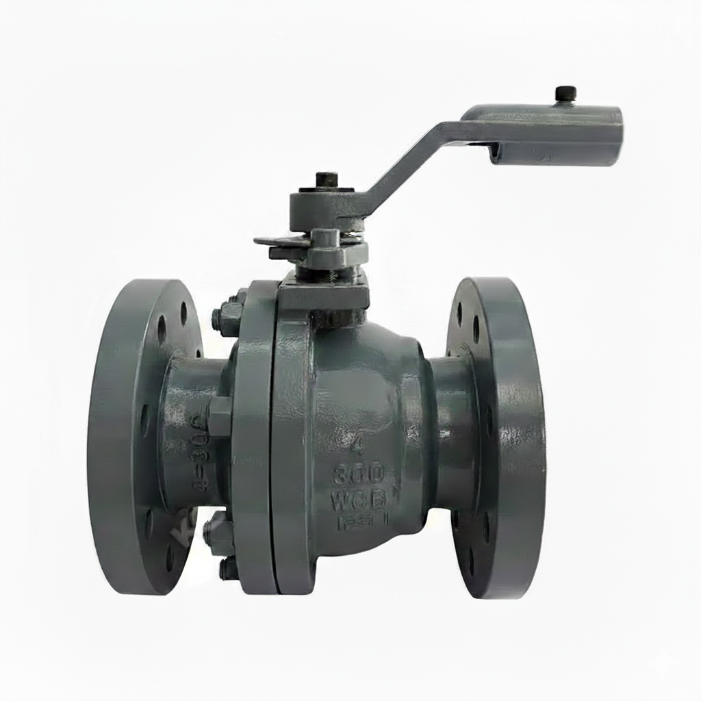
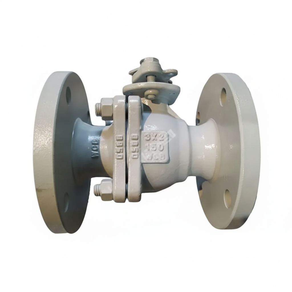
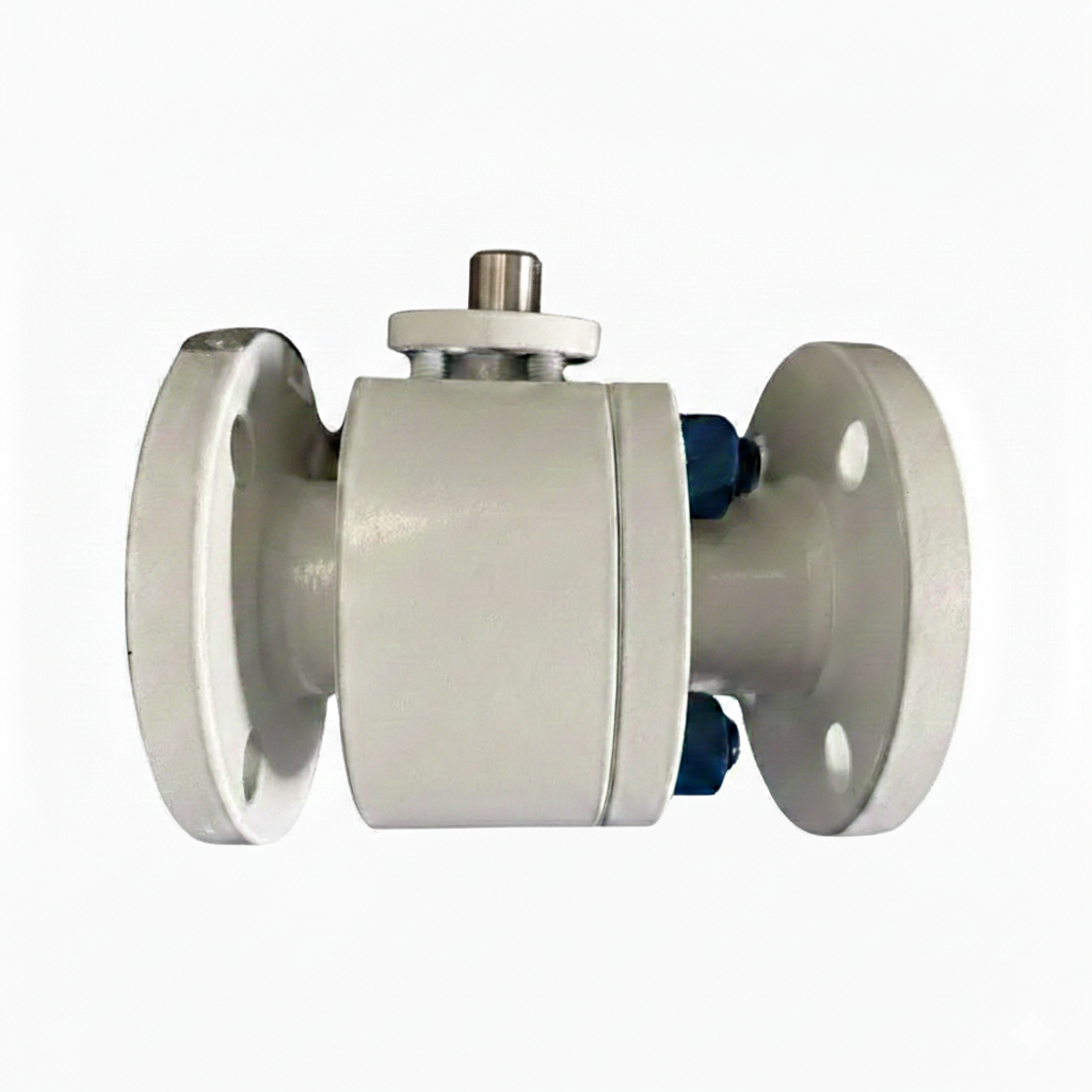
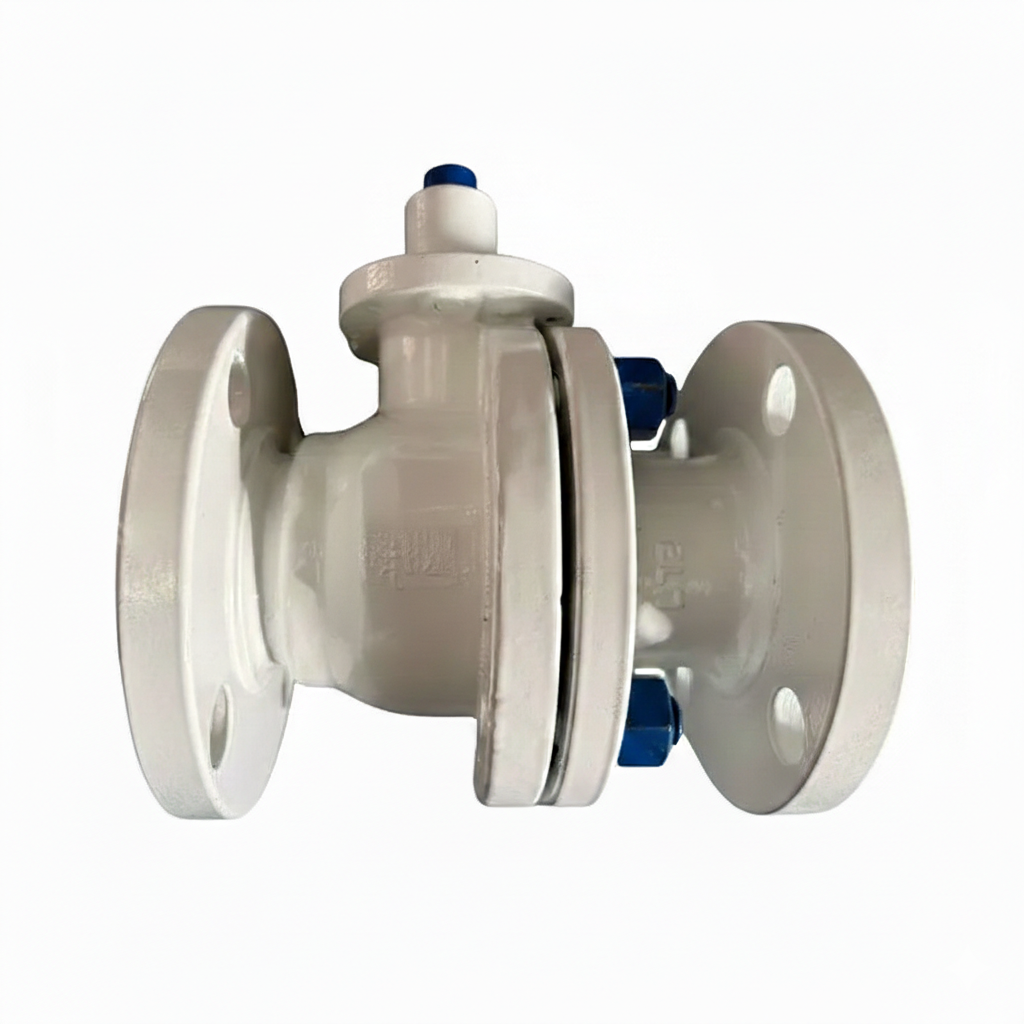
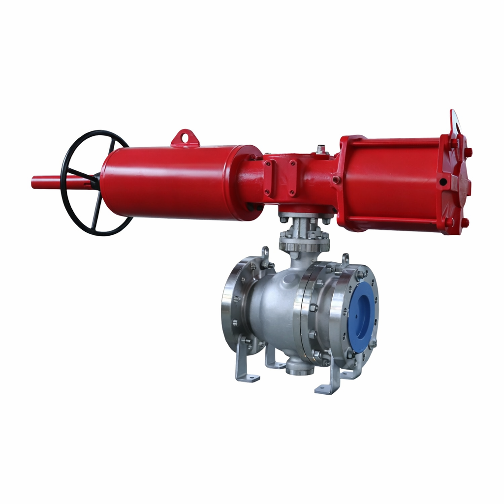
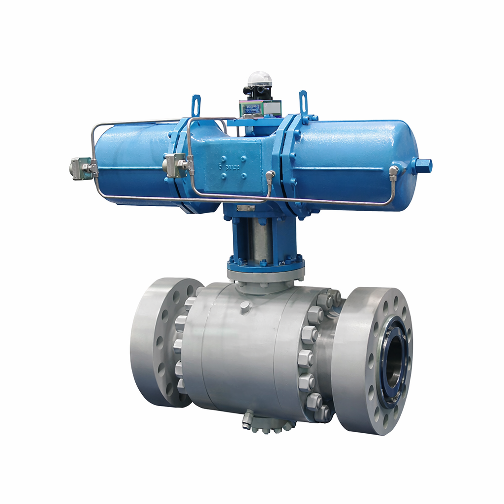
The Pneumatic Actuated Ball Valves Factory specializes in producing high-quality trunnion mounted ball valves with carbon steel bodies (ASTM A105N). These valves are available in sizes ranging from NPS 2 to 48 inches and are designed to handle pressures from Class 150 to 2500 LB. They feature RTJ flanged ends, making them suitable for a wide range of industrial applications requiring reliable and durable flow control solutions.
Model No.: KV-20251229-TMBV-02
Hits: 9
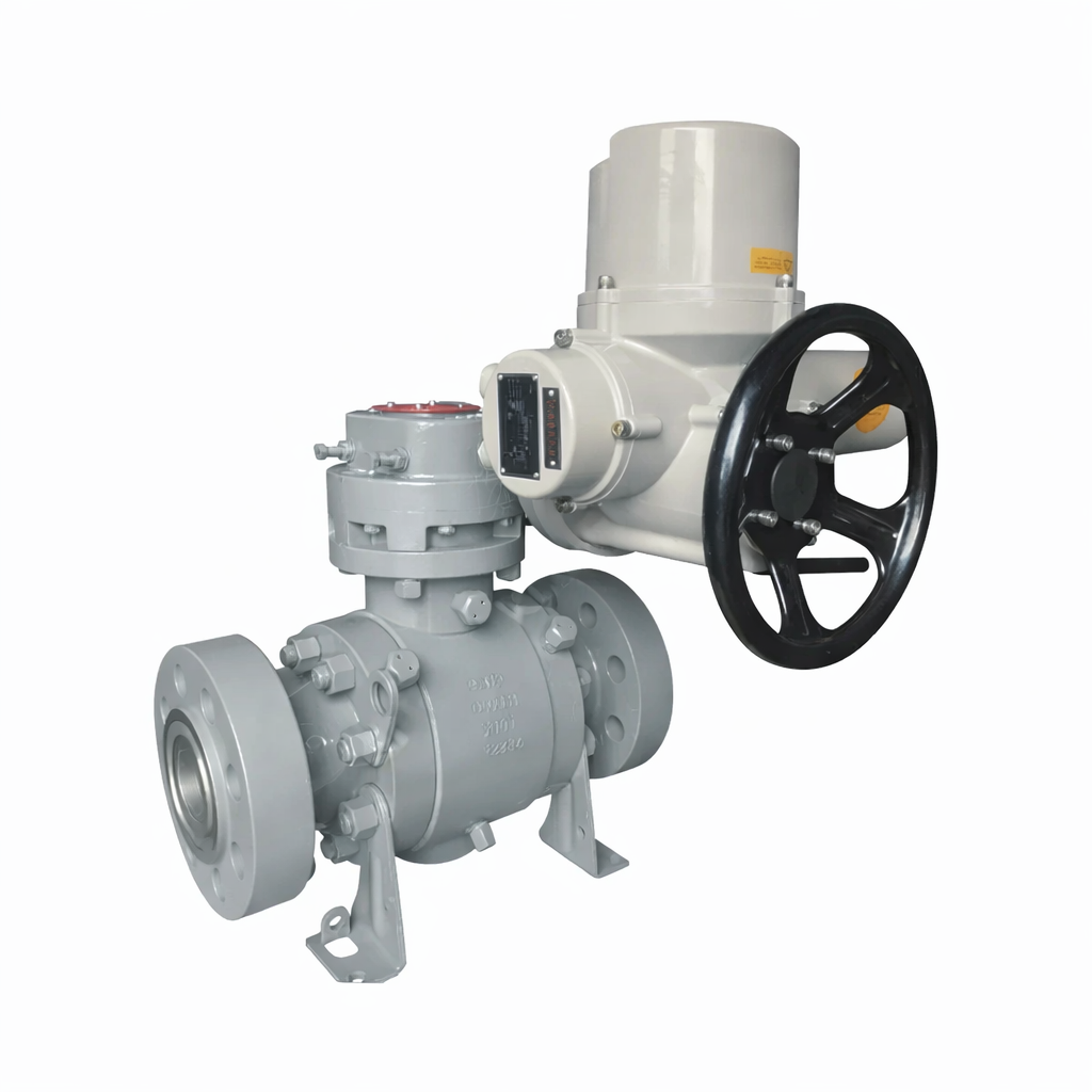
The Electric Actuated Ball Valves Plant offers a robust 65 mm ball valve, trunnion mounted, made from forged carbon steel body (ASTM A105N). This 2-1/2 inch (DN65) valve is designed for high-pressure applications, rated at Class 2500 LB and PN420, ensuring reliable performance and durability in demanding industrial settings.
Model No.: KV-20251229-TMBV-01
Hits: 1
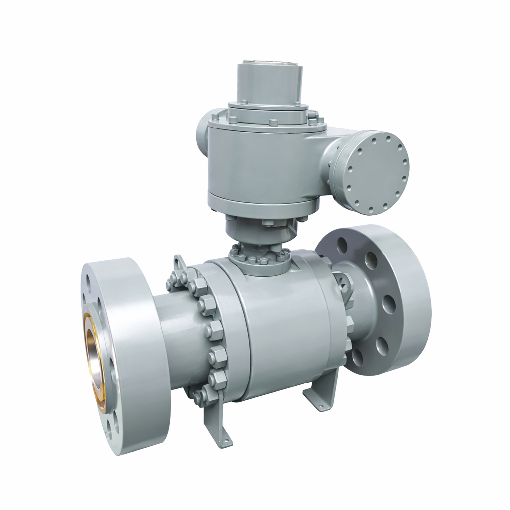
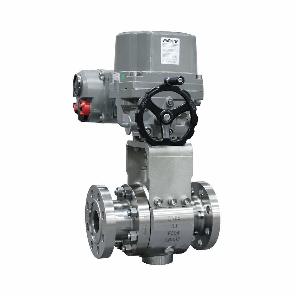
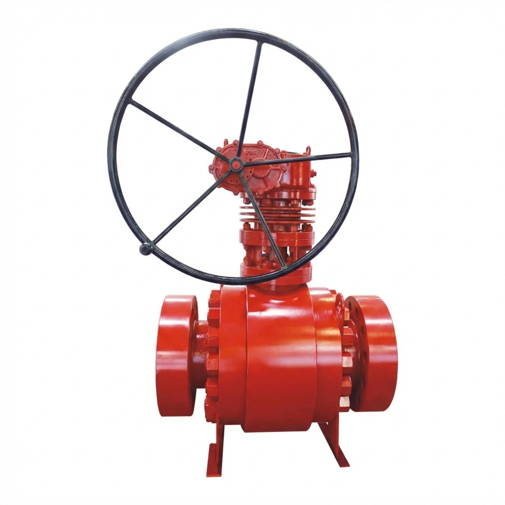
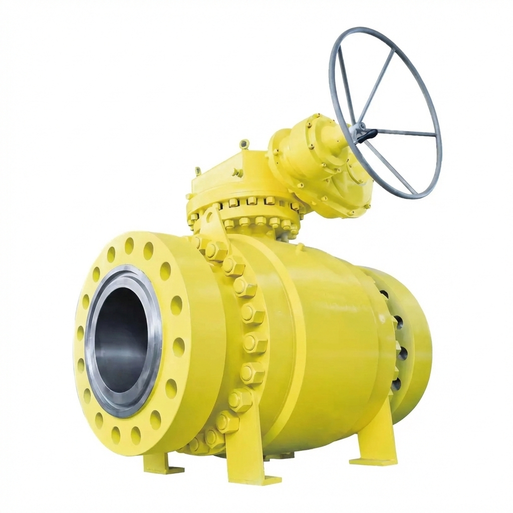
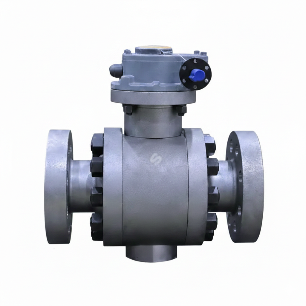
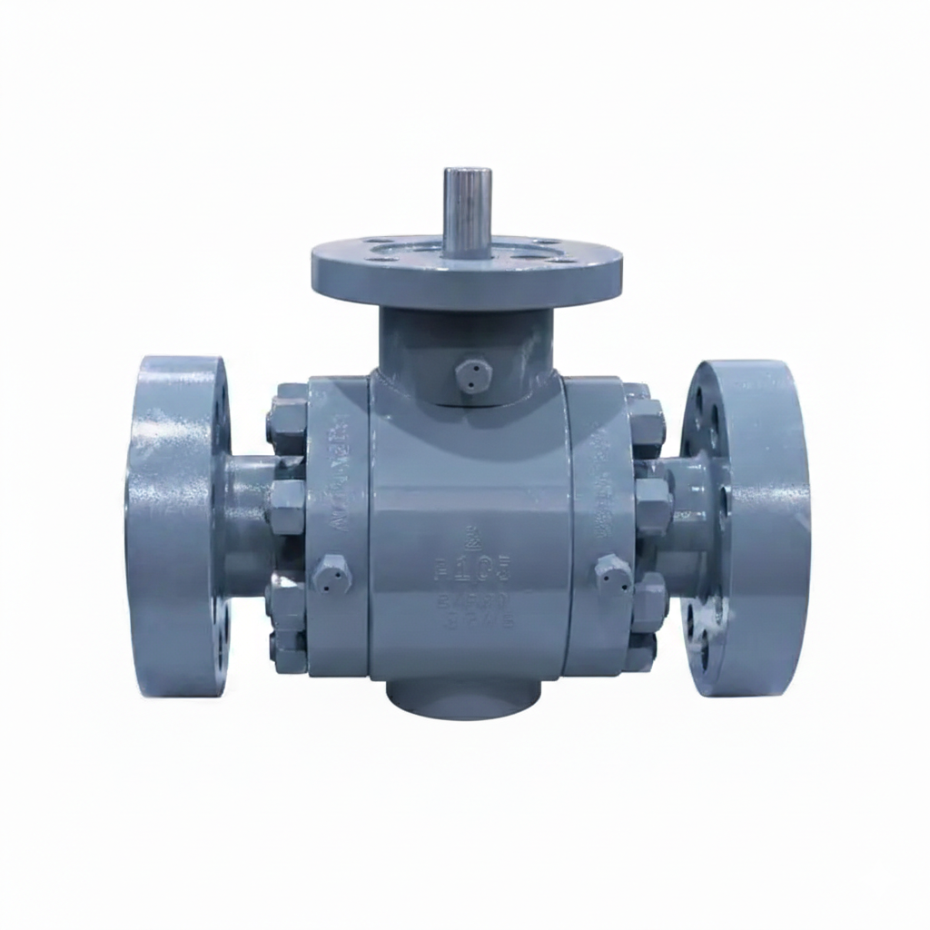
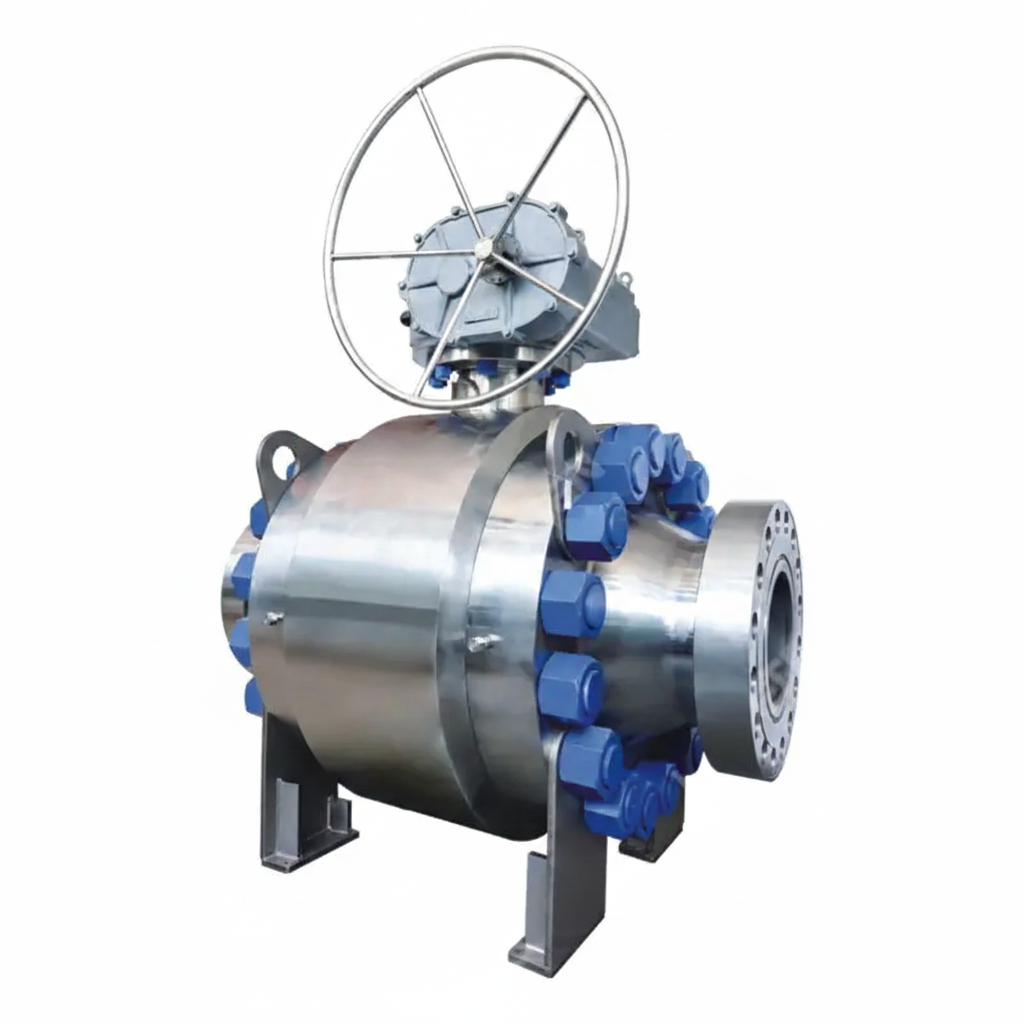
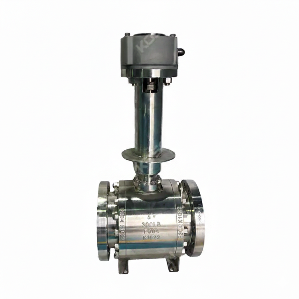
Low-temperature Ball Valve Factory produces high-quality trunnion-mounted ball valves in compliance with API 6D standards. These valves are made from stainless steel ASTM A182 F304, ensuring durability and corrosion resistance. They feature a 6-inch diameter (DN150), a Class 150 LB pressure rating, and a PN20 designation. The flanged ends ensure secure and reliable connections, making them suitable for low-temperature applications.
Model No.: KV-20251212-TMBV-01
Hits: 13
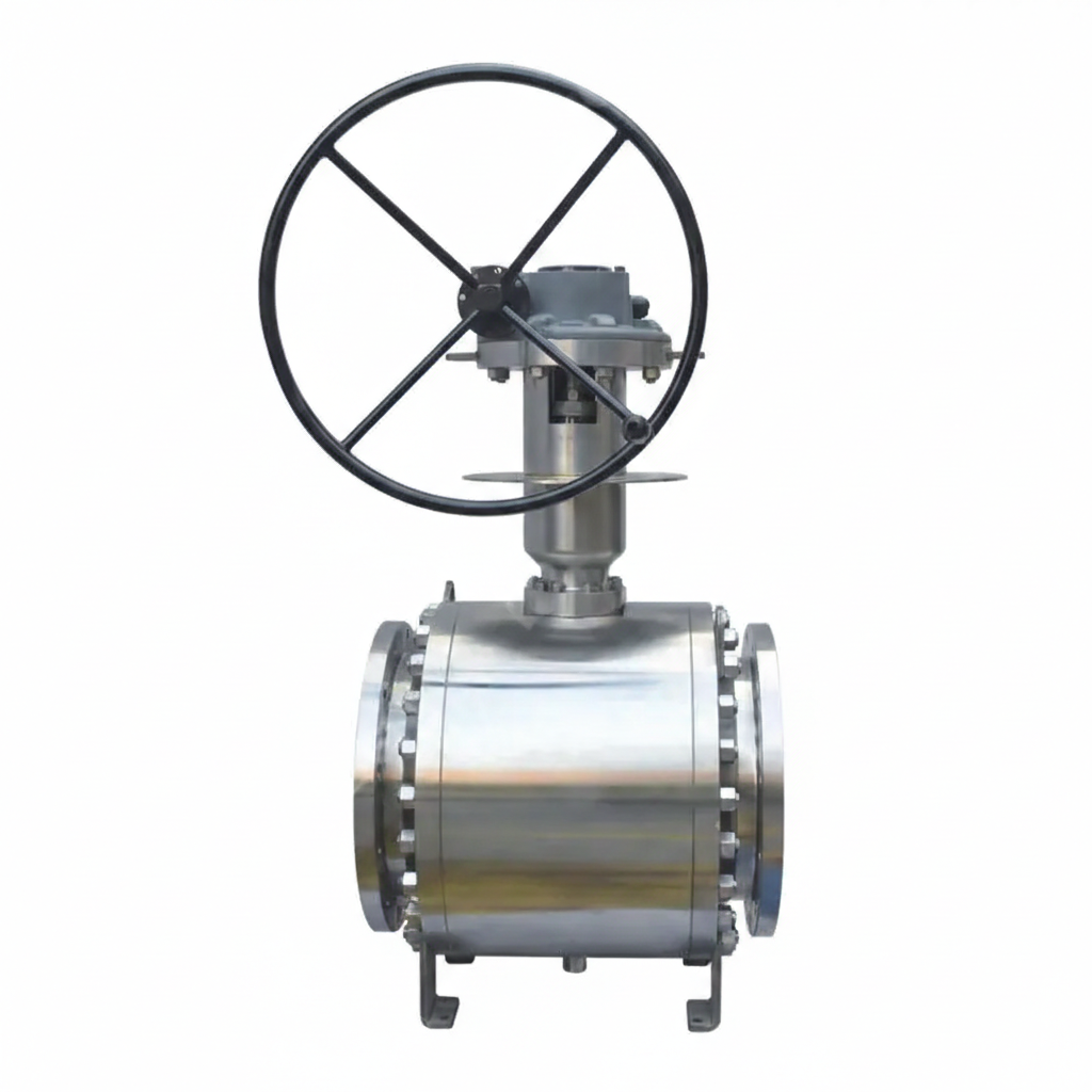
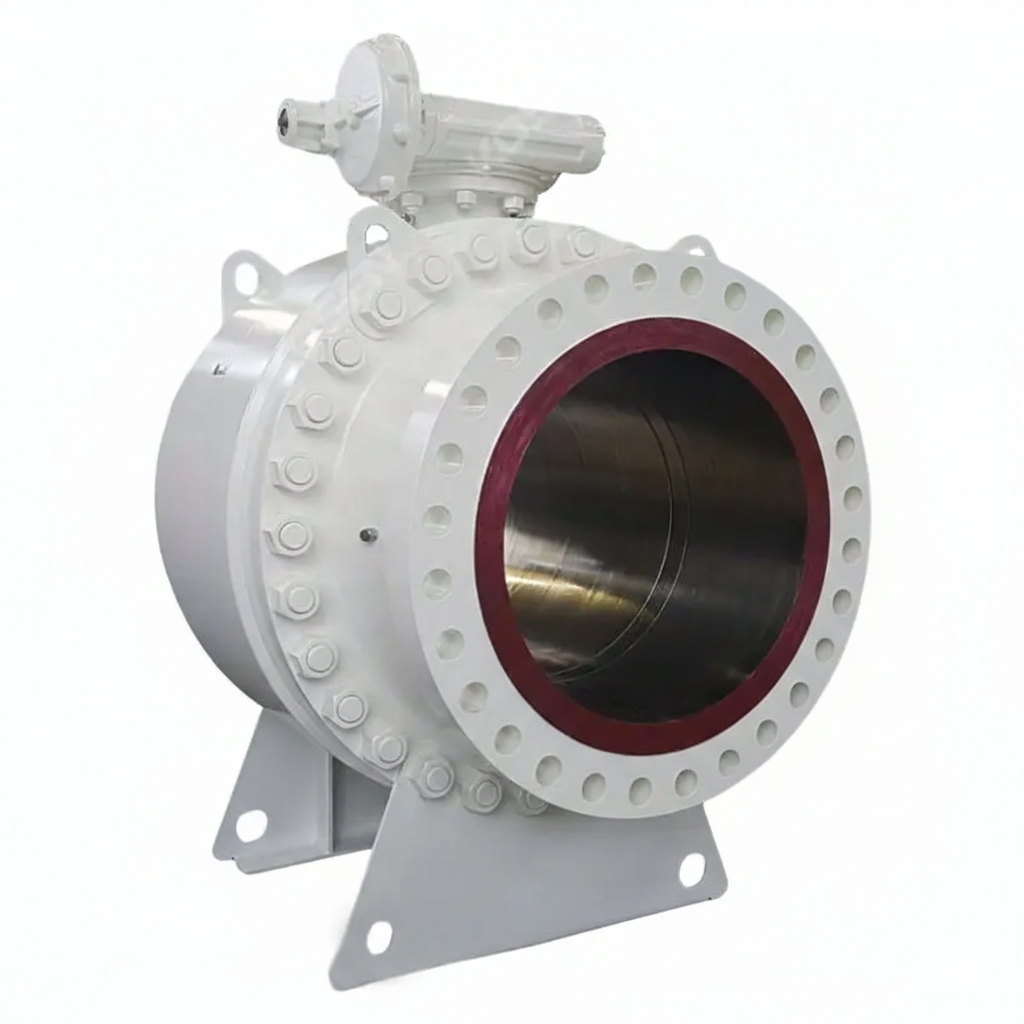
The Custom Trunnion Mounted Ball Valve Plant offers high-quality ball valves designed to meet stringent industry standards such as API 6D and ASTM A105. These valves feature forged carbon steel bodies, ensuring durability and strength. They come with RF flanged ends for secure and reliable connections. The valves are operated using a robust gearbox mechanism, providing precise control and ease of operation.
Model No.: KV-20250701-TMBV-01
Hits: 35
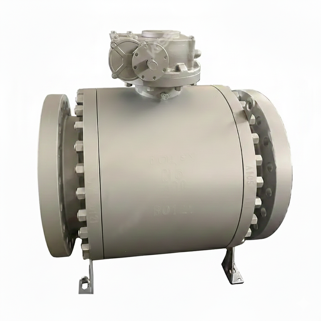
The Forged Steel Trunnion Ball Valve Supplier offers high-quality valves with a trunnion-mounted design, adhering to API 6D standards. These 3-piece, 16-inch valves are made from ASTM A105N carbon steel, ensuring durability and strength. With a pressure rating of Class 300 LB, these valves are designed for heavy-duty applications. The RF flanged ends provide secure and reliable connections, making them ideal for industrial systems requiring robust performance and reliability.
Model No.: KV-20250626-TMBV-02
Hits: 33
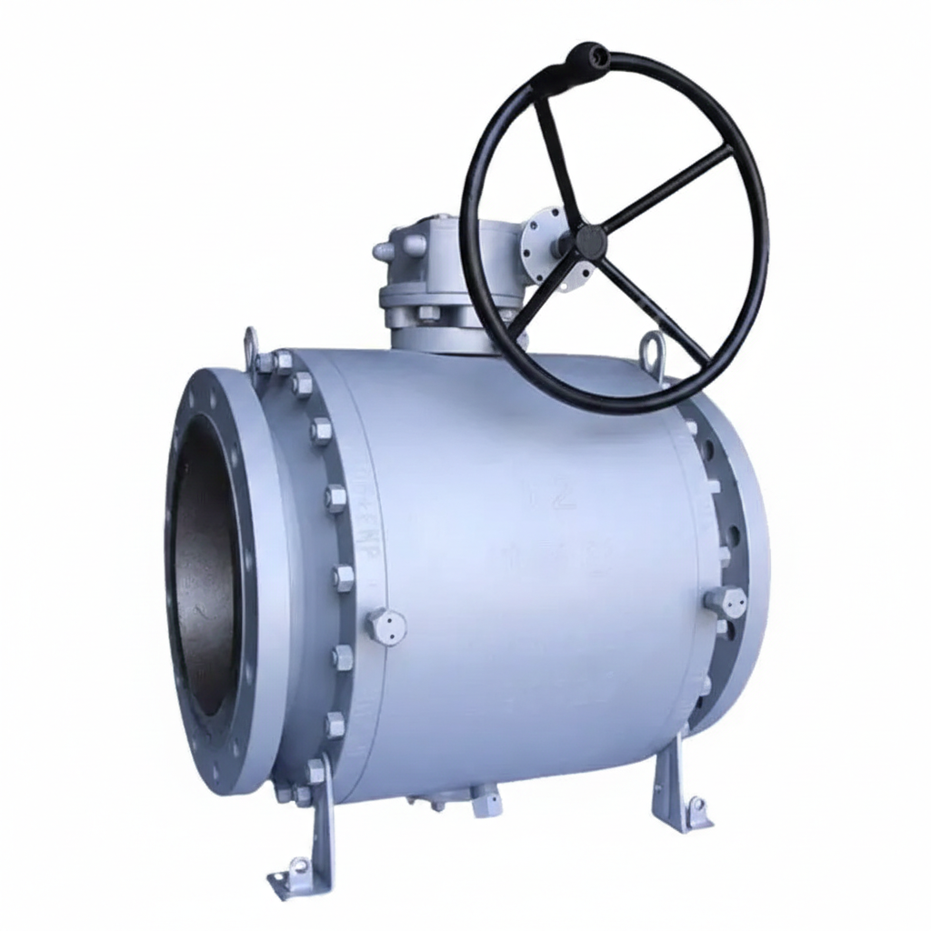
The Carbon Steel Trunnion Mounted Ball Valve Factory produces high-quality valves that meet API 6D and ASTM A105N standards. These 12-inch, DN300 valves are designed for a pressure class of 150 LB and PN20, ensuring reliability in demanding applications. The RF flanged ends facilitate secure and easy connections, while the trunnion-mounted design enhances stability and reduces wear. The inclusion of a gearbox for operation allows for precise control, making these valves suitable for a wide range of industrial uses.
Model No.: KV-20250626-TMBV-01
Hits: 18
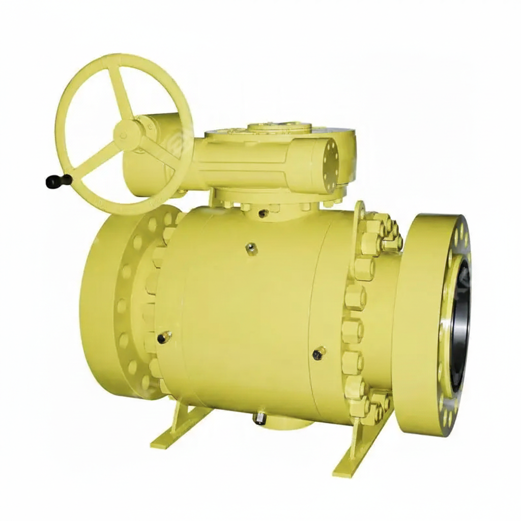
The High Pressure Trunnion Ball Valves Factory produces robust valves designed to meet API 6D standards. These valves are made from ASTM A105N Forged Carbon Steel, ensuring exceptional strength and durability. With a 12-inch (DN300) diameter and rated for Class 1500 LB and PN250 pressure classes, they are built to handle high-pressure applications. The valves feature RTJ flanged end connections for secure and reliable installation. Ideal for demanding industrial environments, these valves offer superior performance and long-term reliability.
Model No.: KV-20250625-TMBV-02
Hits: 7
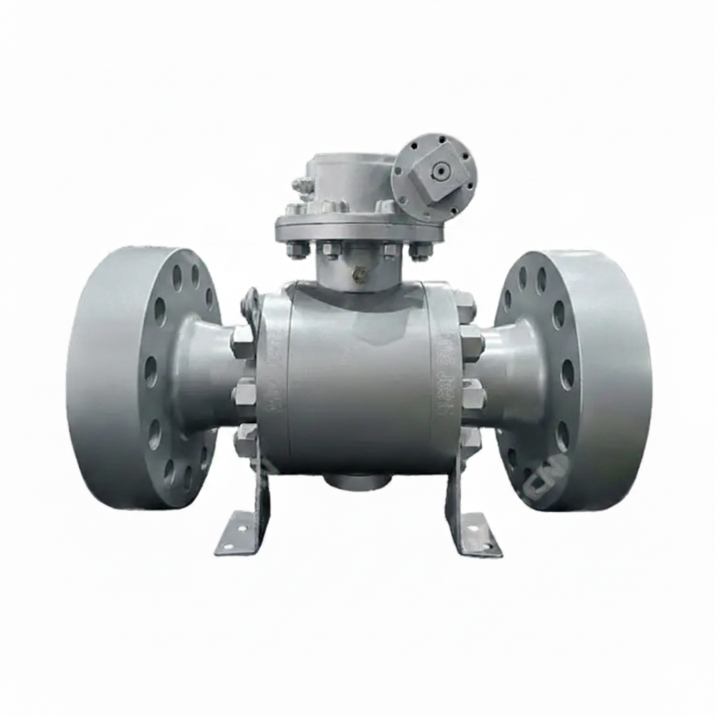
The Reduced Bore Trunnion Ball Valve Plant offers high-quality valves designed to meet stringent industry standards. These valves are manufactured from ASTM A105 Carbon Steel, ensuring durability and reliability. They feature a reduced bore design, which enhances flow efficiency and reduces pressure drop. The valves have a size of 6 inches by 4 inches (DN150 * DN100) and are rated for Class 1500 LB and PN250 pressure classes. They are equipped with RTJ flanged ends for secure and leak-free connections.
Model No.: KV-20250625-TMBV-01
Hits: 13
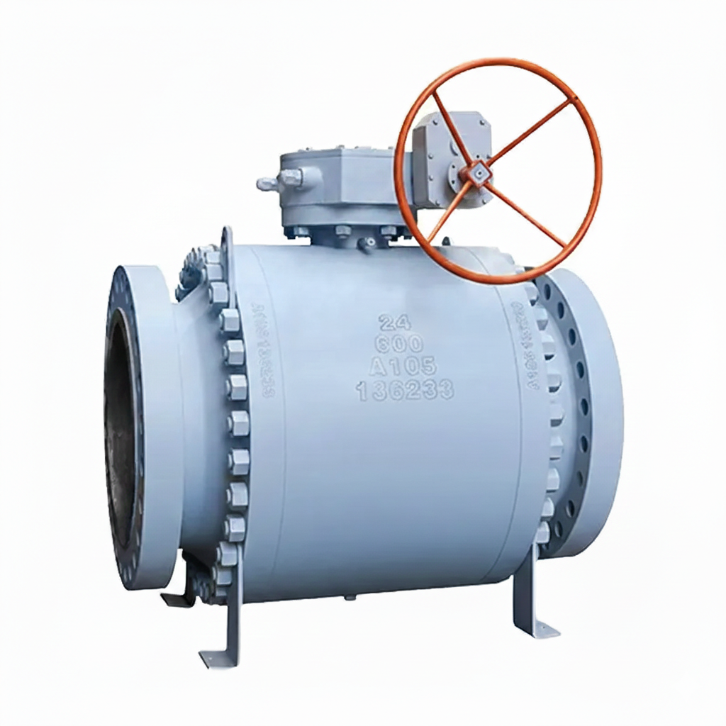
The 3 Piece Trunnion Ball Valves Factory produces high-quality valves designed in accordance with API 6D standards. These valves feature a forged carbon steel body made from ASTM A105 material, ensuring strength and durability. With a 24-inch diameter (DN600) and a pressure rating of 600 LB (PN100), they are suitable for demanding industrial applications. The valves are equipped with raised face (RF) flanged ends for secure and reliable connections.
Model No.: KV-20250623-TMBV-02
Hits: 19

The Side Entry Trunnion Mounted Ball Valve is a high-performance valve designed for critical industrial applications. It complies with API 6D standards and is constructed from ASTM A105N forged carbon steel, ensuring durability and reliability. The valve features a 24-inch diameter (DN600) and a pressure rating of 600 LB (PN100), making it suitable for high-pressure environments. It is equipped with raised face (RF) flanged ends for secure and leak-free connections.
Model No.: KV-20250623-TMBV-01
Hits: 17
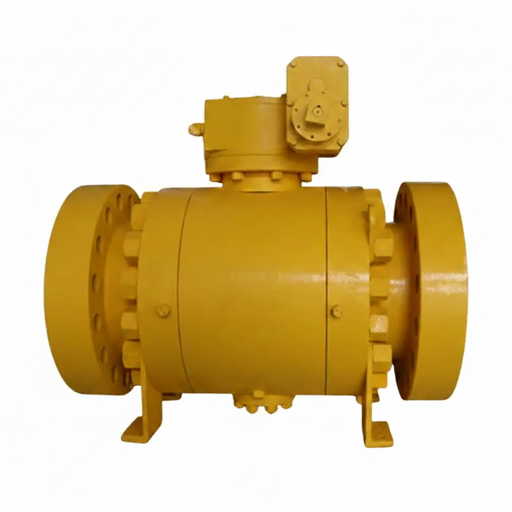
The Class 1500 LB Trunnion Mounted Ball Valve Factory produces high-performance valves designed to meet API 6D standards. These valves feature a 3-piece forged carbon steel body made from ASTM A105 material, ensuring exceptional strength and durability. Available in a 12-inch size with a DN300 and PN250 rating, they are equipped with ring-type joint (RTJ) flanged ends for secure and reliable connections. Each valve comes with a gearbox for smooth and efficient operation.
Model No.: KV-20250620-TMBV-01
Hits: 21
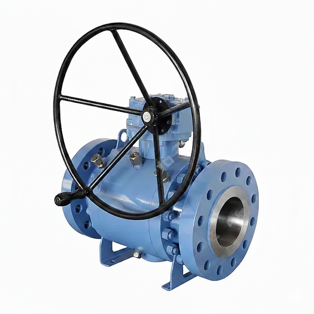
The ASTM A105N Trunnion Mounted Ball Valve Plant offers high-quality valves designed in accordance with API 6D standards. These valves feature forged carbon steel bodies, ensuring durability and strength. They are available in customized sizes and pressure ratings to meet specific requirements. The valves have raised face (RF) flanged ends for secure connections and come equipped with gearboxes for efficient operation.
Model No.: KV-20250620-TMBV-01
Hits: 20
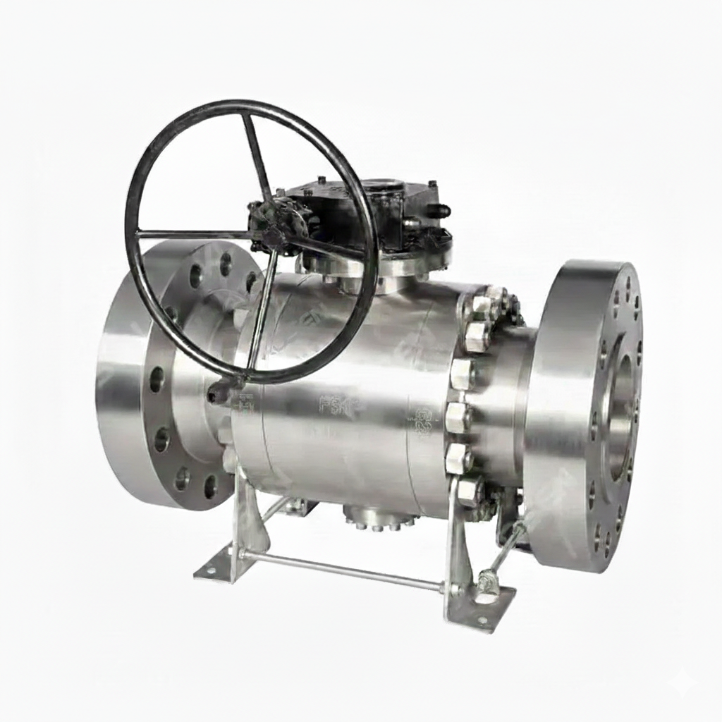
The Duplex Steel Trunnion Ball Valve Factory specializes in manufacturing valves that adhere to API 6D standards, featuring ASTM A182 F51 duplex steel bodies. These valves are available in customized sizes and pressure ratings to meet specific requirements. Equipped with RF flanged ends and operated via a gearbox, they offer enhanced durability and performance, making them suitable for a wide range of industrial applications.
Model No.: KV-20250618-TMBV-02
Hits: 16
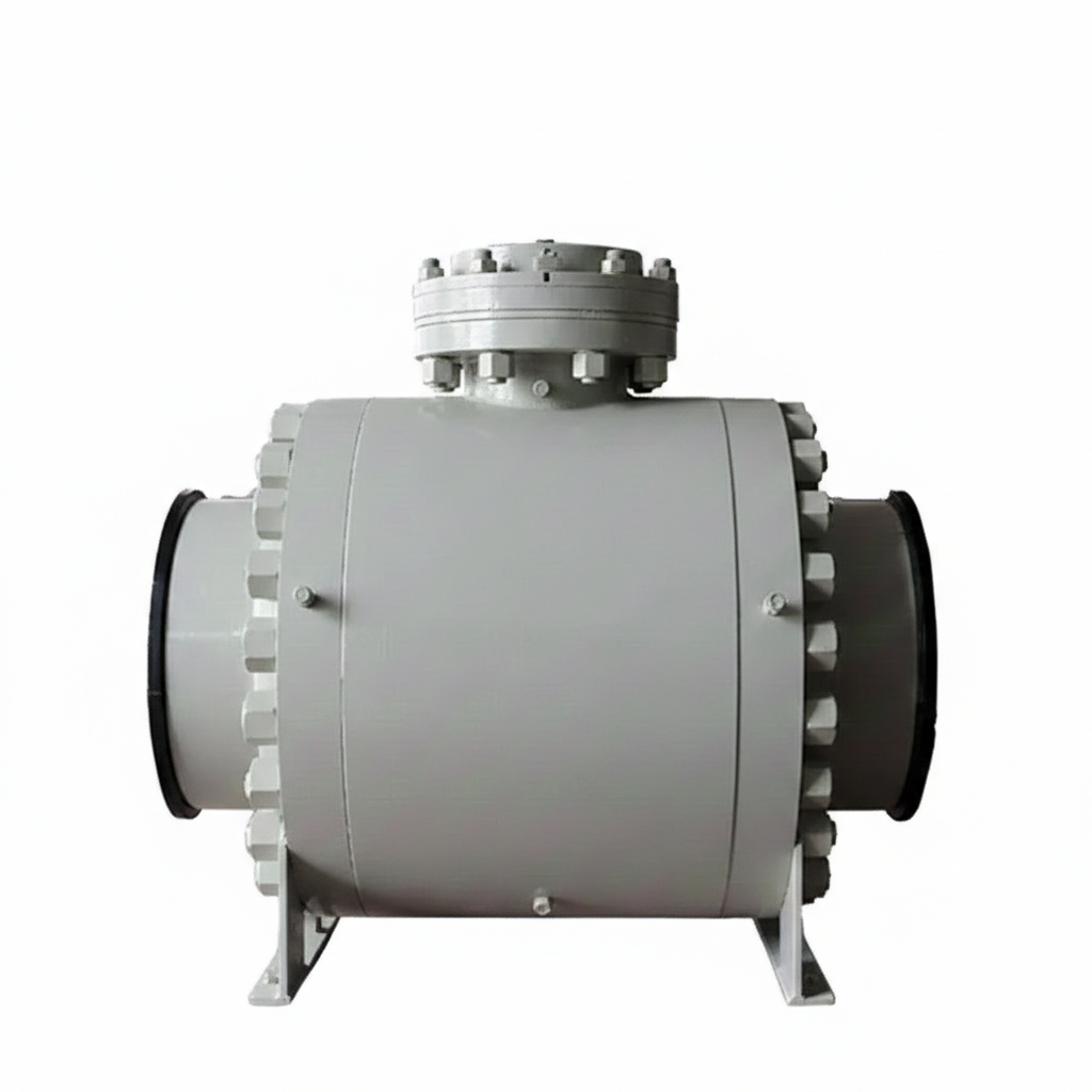
The ASTM A350 LF2 Ball Valves Plant offers high-quality trunnion-mounted ball valves designed to meet API 6D standards. These 3-piece, forged low-temperature carbon steel valves feature a robust 28-inch (DN700) diameter and are rated for Class 600 LB (PN100) pressure. With butt-weld ends, they provide reliable performance in demanding applications, ensuring durability and safety in low-temperature environments.
Model No.: KV-20250618-TMBV-01
Hits: 23
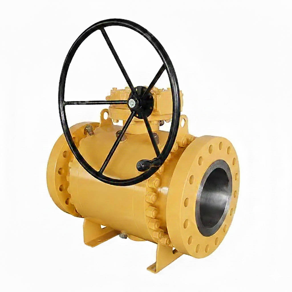
The Three Piece Trunnion Ball Valve Factory specializes in producing high-quality valves that meet API 6D standards. These valves feature an ASTM A105N forged carbon steel body and ASTM A182 F316 trim, ensuring durability and corrosion resistance. Available in customized sizes and pressure ratings, they come with RF flanged ends for secure connections and are operated by a worm gear mechanism, providing reliable and precise control for various industrial applications.
Model No.: KV-20250617-TMBV-02
Hits: 12
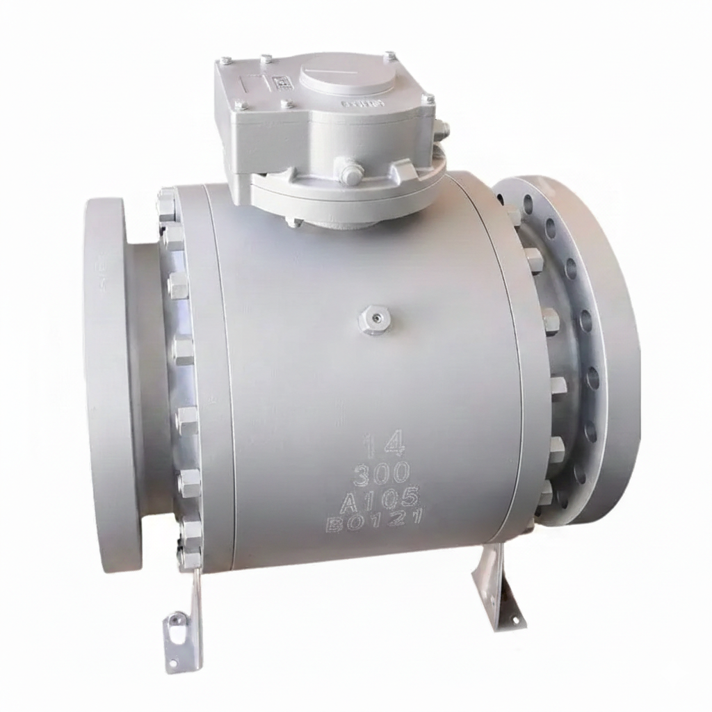
The ASTM A105 Trunnion Mounted Ball Valves Plant offers high-quality forged carbon steel valves designed for rugged industrial applications. These valves feature a 14-inch diameter (DN350) and are rated for a pressure class of 300 LB (PN50), ensuring durability and reliability. They comply with API 6D standards and come with RF flanged ends for secure connections. The inclusion of a gearbox facilitates smooth operation.
Model No.: KV-20250617-TMBV-01
Hits: 22
The high-pressure ball valves, specializing in trunnion-mounted designs that adhere to API 6D standards. Our valves feature forged carbon steel bodies made from ASTM A105N material, ensuring exceptional strength and durability. Available in NPS 8 inch (DN200) size, these valves are rated for Class 2500 LB and PN420 pressure classes, making them suitable for high-pressure applications. They are equipped with RTJ (Ring-Type Joint) connections for secure and leak-tight performance.
Model No.: KV-20250616-TMBV-02
Hits: 21
The API 6D Trunnion Mounted Ball Valve, supplied by a reputable manufacturer, features a robust ASTM A105N body with Inconel 625 cladding for enhanced corrosion resistance. Available in customized sizes, this valve is designed for high-pressure applications, rated at 900 LB and PN150, ensuring durability and reliability. It comes with RF flanged ends for secure connections and a bare stem for easy maintenance and inspection.
Model No.: KV-20250616-TMBV-01
Hits: 16
The ASTM A105N Fixed Ball Valve Manufacturer specializes in producing high-quality 3-piece trunnion-mounted ball valves that adhere to API 6D standards. These valves are crafted from forged carbon steel, ensuring exceptional strength and durability. With a 20-inch (DN500) diameter and rated for Class 150 LB (PN20) pressure, these valves are designed for demanding industrial applications. The RF flanged ends provide secure and reliable connections.
Model No.: KV-20250613-TMBV-02
Hits: 20
The API 6D Fixed Ball Valve Supplier offers robust trunnion-mounted ball valves with ASTM A216 WCB carbon steel bodies, designed for heavy-duty industrial applications. These 12-inch (DN300) valves are rated at Class 150 LB (PN20), ensuring they can handle significant pressure. The RF flanged ends facilitate easy installation and integration into existing pipeline systems. With their trunnion-mounted design, these valves provide enhanced stability and reliability, making them ideal for critical applications requiring high performance and durability.
Model No.: KV-20250613-TMBV-01
Hits: 40
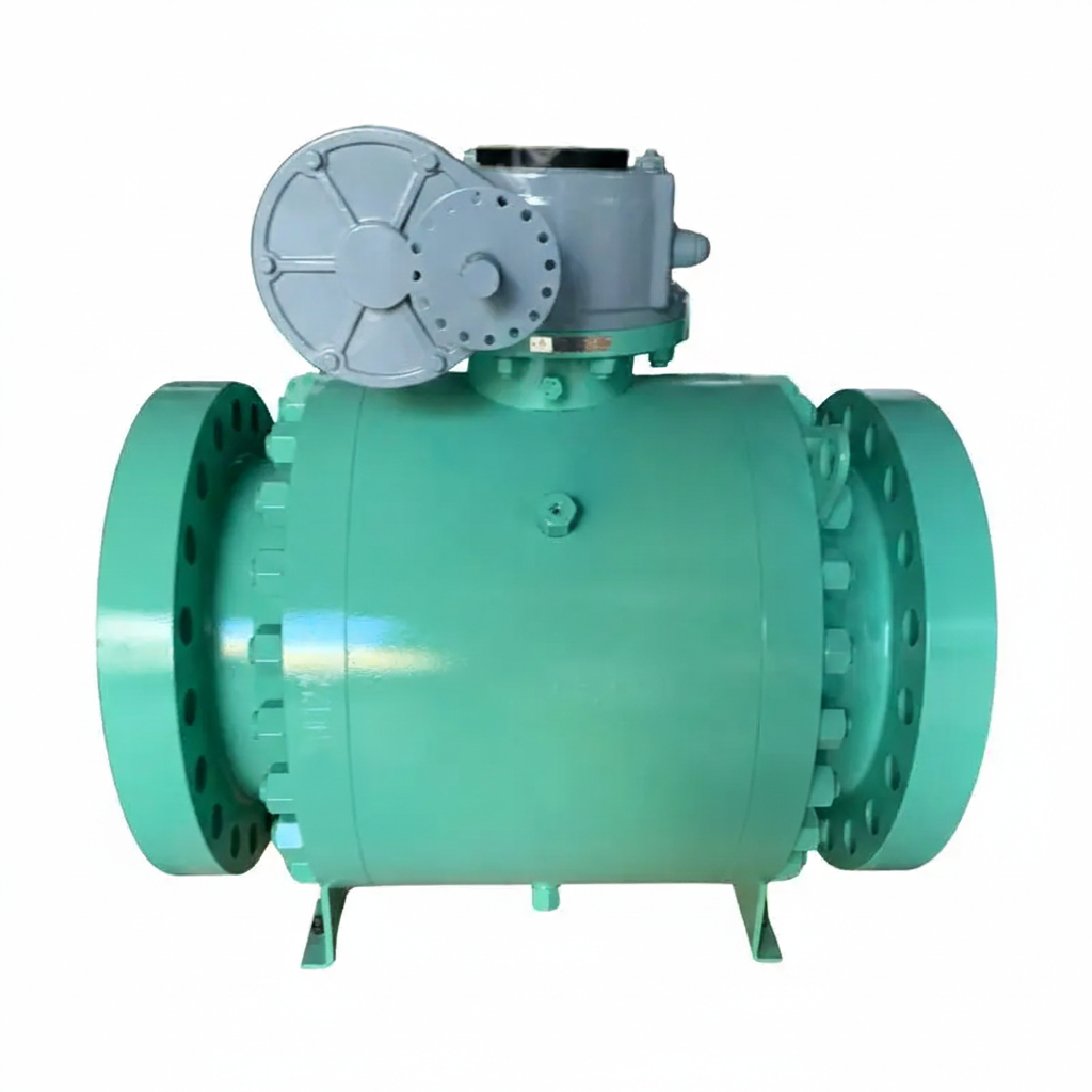
The Full Bore Trunnion Ball Valve Plant specializes in manufacturing high-quality valves designed in accordance with API 6D standards. These valves feature a 3-piece forged carbon steel body made from ASTM A105N material, ensuring durability and strength. They are available in customized sizes and pressure ratings to meet specific requirements. The valves come with raised face (RF) flanged ends for secure and reliable connections, making them suitable for a wide range of industrial applications.
Model No.: KV-20250609-TMBV-02
Hits: 10

The ASTM A351 CF8 Ball Valve is a high-quality trunnion mounted valve designed for robust performance. It features a 2-piece body construction, adhering to API 6D standards. Available in DN250 (10-inch) size with a PN40 pressure rating and Class 300 LB pressure class, this valve is equipped with a gear box for smooth operation and has raised face (RF) flanged ends for secure connections.
Model No.: KV-20250609-TMBV-01
Hits: 9
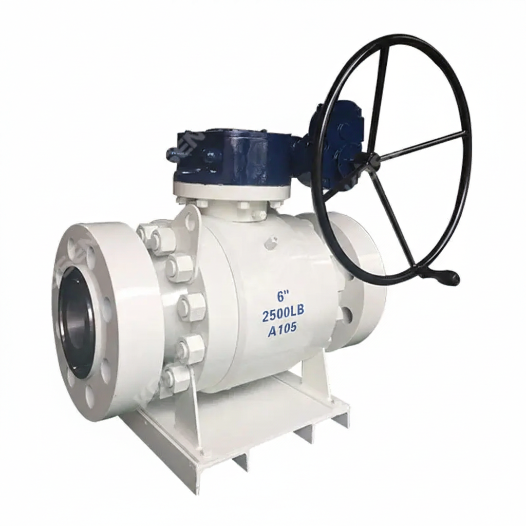
The High Pressure Fixed Ball Valve Plant offers a robust Trunnion Mounted Ball Valve designed to meet stringent industry standards. This valve is constructed from high-quality Forged Carbon Steel ASTM A105, ensuring durability and reliability. With a 6-inch diameter (DN150) and a pressure rating of Class 2500 LB (PN420), it is engineered to handle high-pressure applications. The valve complies with API 6D specifications and features RTJ (Ring Type Joint) ends for secure and leak-free connections.
Model No.: KV-20250607-TMBV-01
Hits: 27
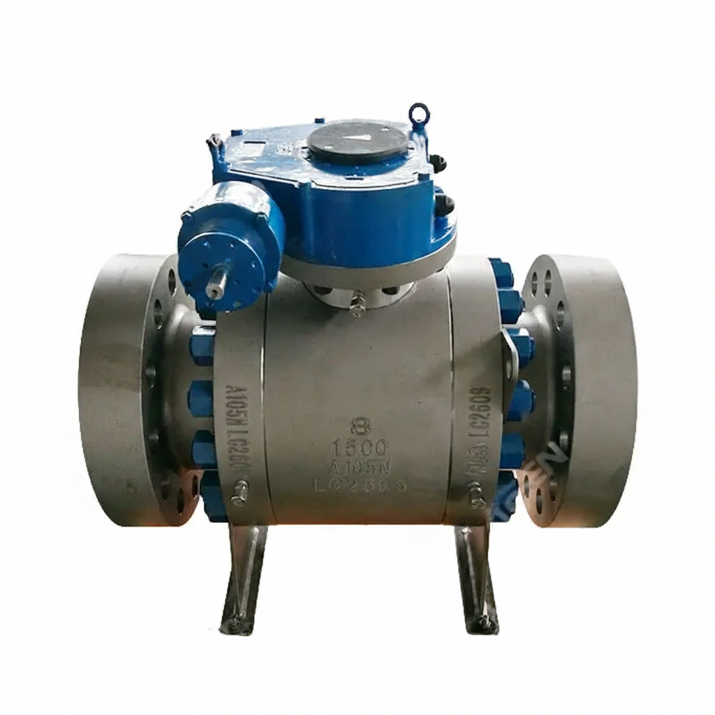
The 3-piece Trunnion Mounted Ball Valve is manufactured to API 6D standards, featuring a Carbon Steel ASTM A105N body. It has an 8-inch (DN200) size and a pressure rating of Class 1500 LB (PN250). The valve is equipped with RTJ flanged ends for secure connections and operates via a gear box for precise control. This design ensures durability, reliability, and efficient operation in demanding industrial applications.
Model No.: KV-20250605-TMBV-02
Hits: 11
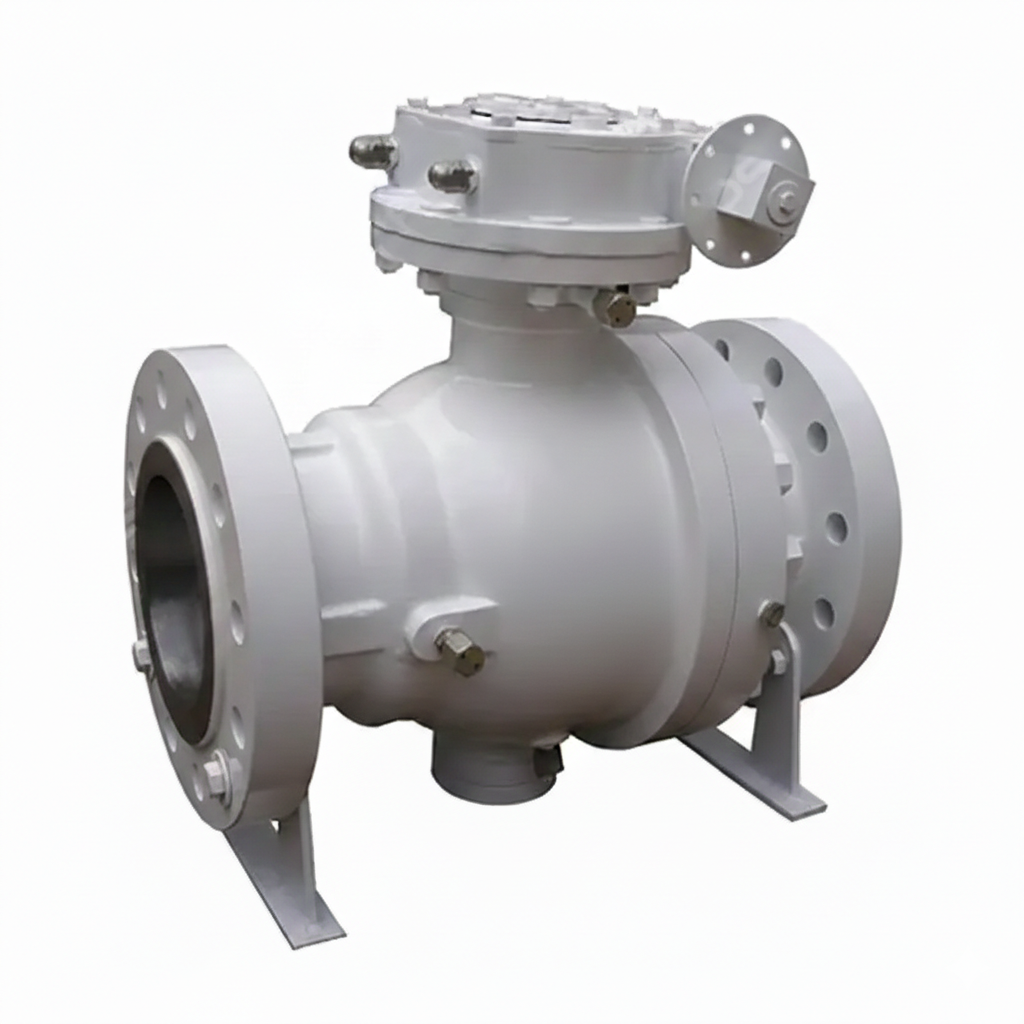
The API 6D Trunnion Mounted Ball Valve is a high-performance valve designed for critical pipeline applications. Manufactured with a Cast Carbon Steel Body (ASTM A216 WCB), it offers excellent strength and durability. With an 8-inch (DN200) size and a pressure rating of 600 LB (PN100), this valve is suitable for high-pressure systems. The trunnion-mounted design ensures stable operation and reduced wear. It features RF flanged ends for secure connections and is operated by a worm gear mechanism, providing precise control.
Model No.: KV-20250605-TMBV-01
Hits: 11
The GOST Trunnion Mounted Ball Valve Factory produces high-quality valves designed to meet API 6D standards, featuring ASTM A216 WCB cast carbon steel bodies. These valves are available in a 20-inch (DN500) size with a pressure rating of PN16 (Class 150 LB), making them suitable for high-pressure applications. They feature RF flanged ends for secure connections and are operated via a gearbox for reliable control.
Model No.: KV-20250529-TMBV-02
Hits: 23
The 3 Piece Trunnion Mounted Ball Valve Supplier offers a high-quality valve designed to API 6D standards, featuring an ASTM A105N forged carbon steel body. This valve has a 16-inch (DN400) size and a pressure rating of 300 LB (PN50), making it suitable for demanding industrial applications. It features RF flanged ends for secure connections and is operated via a gearbox for reliable control. The trunnion-mounted design ensures the ball remains securely in place under high pressure, providing smooth operation and long service life.
Model No.: KV-20250529-TMBV-01
Hits: 11
The Orbit Rising Stem Ball Valve Factory produces high-quality ball valves designed to meet API 6D standards. These valves are made from ASTM A352 LCC low-temperature carbon steel, ensuring durability and reliability in demanding applications. With an 8-inch (DN200) diameter and rated at Class 300 LB and PN50 pressure classes, they feature raised face (RF) flanged ends for secure connections. The valves are operated using a bevel gear mechanism, providing smooth and precise control.
Model No.: KV-20250526-TMBV-02
Hits: 100
The 3 Piece Cryogenic Ball Valve Plant specializes in producing high-performance trunnion mounted ball valves designed for cryogenic applications. These valves conform to API 6D standards and are made from ASTM A350 LF2 low-temperature carbon steel, ensuring durability and reliability in extreme cold conditions. With a 6-inch (DN150) diameter and rated at Class 1500 LB and PN250 pressure classes, they feature ring-type joint (RTJ) flanged ends for secure connections. The valves come equipped with a gearbox for smooth and precise operation.
Model No.: KV-20250526-TMBV-01
Hits: 28
The ASTM A182 F316 Cryogenic Ball Valves Factory produces high-quality trunnion-mounted ball valves designed for cryogenic applications. These valves are forged from stainless steel, ensuring durability and resistance to low temperatures. They comply with API 6D standards and feature an 8-inch (DN200) size with a Class 600 LB pressure rating and a PN100 nominal pressure. Each valve is equipped with a gearbox for smooth operation and has a raised face (RF) connection. These valves are ideal for demanding cryogenic systems, offering reliability and long-term performance.
Model No.: KV-20250522-TMBV-02
Hits: 14
The ASTM A350 LF2 Cryogenic Ball Valve Plant offers a robust solution for low-temperature applications. This trunnion-mounted ball valve is designed to meet API 6D standards, ensuring reliability and performance. Constructed from low-temperature carbon steel, it features a large 18 x 16-inch (DN450 x DN400) size with a Class 600 LB pressure rating and a PN100 nominal pressure. The valve has a raised face (RF) connection, making it suitable for high-pressure cryogenic systems.
Model No.: KV-20250522-TMBV-01
Hits: 56
The Bronze Trunnion Mounted Ball Valve Manufacturer produces high-quality valves that adhere to API 6D standards. These valves feature a durable ASTM B150 C63200 bronze body, ensuring excellent corrosion resistance and mechanical strength. Available in a 2-inch (DN50) size, they are rated for a pressure class of 150 LB (PN20). The valves come with flanged end connections for secure installation and feature a bare stem design, making them suitable for a variety of industrial applications.
Model No.: KV-20250520-TMBV-02
Hits: 10
The Duplex Steel Ball Valve is high-performance trunnion-mounted ball valves that comply with API 6D standards. These valves feature a robust ASTM A890 4A body, providing excellent strength and corrosion resistance. Available in a large 24-inch (DN600) size, they are rated for a pressure class of 300 LB (PN50). The valves come with RF (Raised Face) flanged ends for secure and reliable connections, making them ideal for demanding industrial applications.
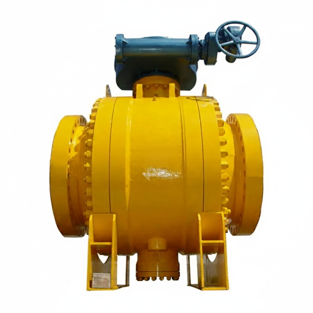
The ASTM A352 LCB Ball Valve Factory specializes in producing robust trunnion-mounted ball valves with a 3-piece body design, adhering to API 6D standards. These valves are crafted from low-temperature carbon steel, ensuring performance in demanding conditions. Available in a large 56-inch size with a Class 600 LB rating, they feature RF flanged ends, making them suitable for high-pressure applications in various industries.
Model No.: KV-20250519-TMBV-02
Hits: 31
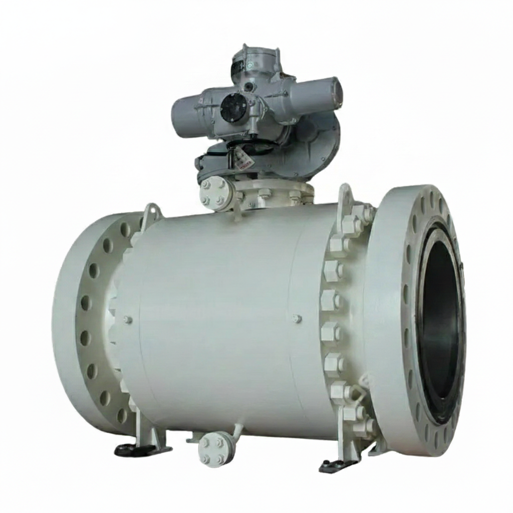
The Electric Actuated Ball Valve Plant offers high-quality 3-piece forged steel ball valves, designed to meet API 6D standards. These valves are made from carbon steel ASTM A105N, ensuring durability and reliability. They feature RTJ flanged ends and are available in customized sizes and pressure ratings to meet specific industrial requirements.
Model No.: KV-20250519-TMBV-01
Hits: 11
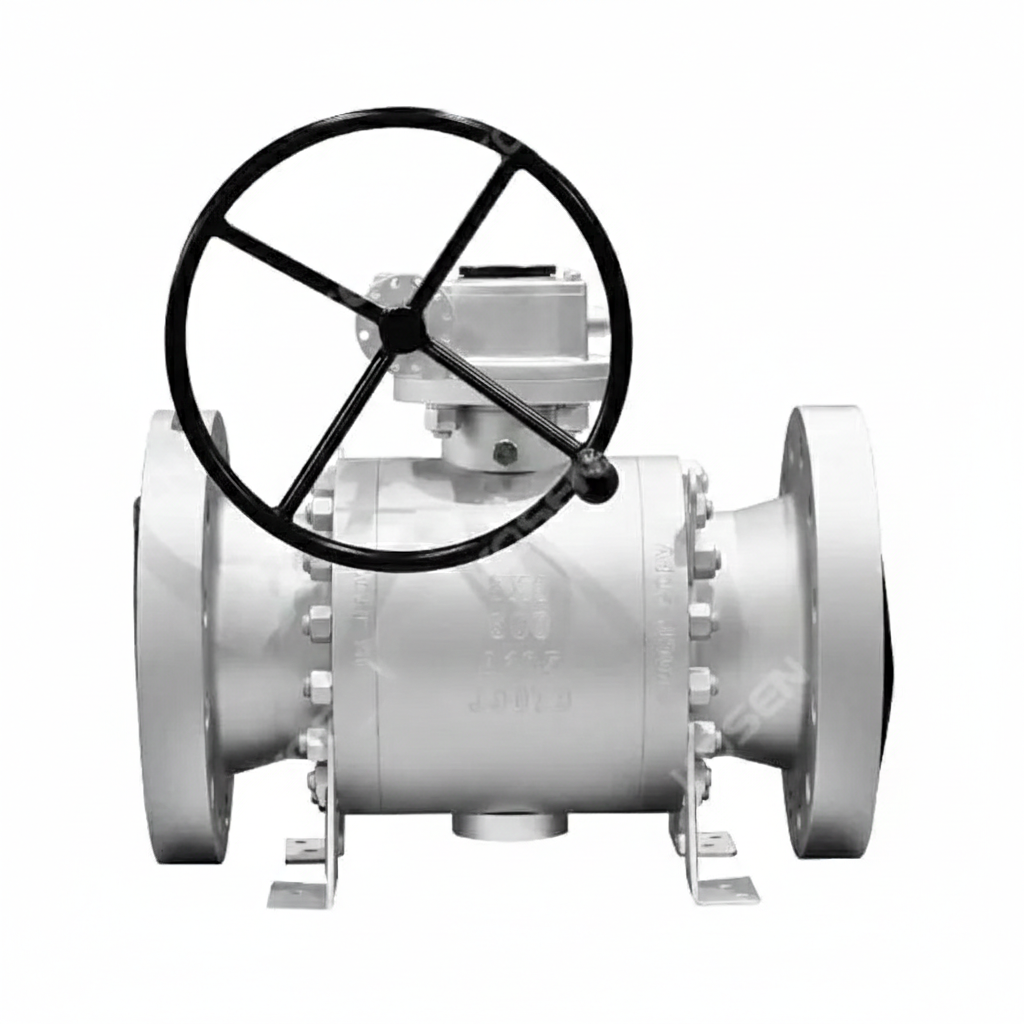
The Reduced Bore Ball Valve Factory specializes in producing high-quality ball valves with a trunnion-mounted design, ensuring stability and reliability. These valves comply with the API 6D standard and are made from ASTM A105N forged carbon steel, offering durability and strength. The reduced bore design features an 8-inch inlet (DN200) and a 6-inch outlet (DN150), with a pressure rating of 600 LB and PN100. The raised face (RF) flanged ends ensure secure and leak-free connections.
Model No.: KV-20250514-TMBV-02
Hits: 20
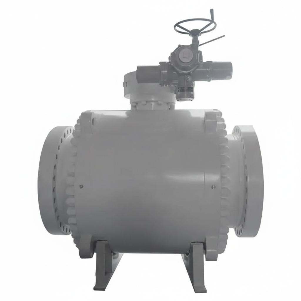
This fixed ball valve features a 3-piece body construction, ensuring durability and ease of maintenance. It adheres to the stringent API 6D standard, guaranteeing high performance and safety. Made from forged carbon steel ASTM A105N, the valve is designed for heavy-duty use, with a large 40-inch diameter (DN1000) and a pressure rating of 600 LB. The raised face (RF) flanged connections ensure secure and leak-free integration into existing pipelines. Equipped with an electric actuator, it provides precise control and automation capabilities.
Model No.: KV-20250514-TMBV-01
Hits: 7
The 3-piece Fixed Ball Valve Factory specializes in producing high-quality Trunnion Mounted Ball Valves that adhere to API 6D standards. These valves are crafted from forged carbon steel, specifically ASTM A105N, ensuring exceptional strength and durability. With a 16-inch (DN400) diameter and rated for Class 600 LB and PN100 pressure classes, these valves are designed for demanding industrial applications. The RF (Raised Face) flanged ends provide secure and reliable connections.
Model No.: KV-20250512-TMBV-02
Hits: 20
The Reduced Bore Ball Valve Plant offers a high-performance Trunnion Mounted Ball Valve designed to meet stringent industry standards. This valve is manufactured in accordance with API 6D and ASTM A350 LF2 specifications, ensuring durability and reliability. It features a reduced bore with dimensions of 24 inches (DN600) on the inlet and 20 inches (DN500) on the outlet, providing efficient flow control. The valve is rated for a pressure class of 600 LB and PN100, making it suitable for high-pressure applications. It also features RF (Raised Face) ends for secure connections.
Model No.: KV-20250512-TMBV-01
Hits: 32
The ASTM A182 F51 Ball Valves Factory produces high-performance trunnion-mounted ball valves designed to API 6D standards. These valves feature a duplex stainless steel body, offering excellent corrosion resistance and mechanical strength. With a 12-inch diameter and a pressure class of 1500 LB, they are ideal for demanding industrial applications. The RTJ flanged ends ensure secure and leak-tight connections, making these valves suitable for critical systems requiring high reliability and durability.
Model No.: KV-20250509-TMBV-02
Hits: 52
The Three Piece Ball Valve Plant offers a robust solution for high-pressure applications. This trunnion-mounted ball valve is designed to API 6D standards, ensuring reliability and performance. Crafted from forged carbon steel ASTM A105N, it features a 12-inch diameter (DN300) and a pressure class of 900 LB, making it suitable for demanding industrial environments. The valve is equipped with RTJ flanged ends for secure connections. Its three-piece construction allows for easy maintenance and inspection, enhancing its durability and versatility.
Model No.: KV-20250509-TMBV-01
Hits: 11
The Carbon Steel Ball Valve Factory produces heavy-duty trunnion mounted ball valves built to API 6D specifications. Constructed from ASTM A105 carbon steel, each valve features a large 36-inch (DN900) size, supports high-pressure Class 600 LB / PN100 ratings, and comes with RF flanged ends, making it ideal for critical flow control in pipelines, oil and gas, and industrial systems.
Model No.: KV-20250507-TMBV-02
Hits: 51
The Reduced Bore Ball Valve Plant in China manufactures high-performance valves built to API 6D standards with a robust trunnion-mounted design. Crafted from corrosion-resistant ASTM A182 F51 duplex stainless steel, each valve features a 6 × 4 inch (DN150 × DN100) reduced bore configuration, Class 150 LB / PN20 pressure rating, and RF flanged ends, making it ideal for demanding flow control applications in oil, gas, and petrochemical industries.
Model No.: KV-20250507-TMBV-01
Hits: 19
The Multi-Way Ball Valve is designed for versatile fluid control in various industrial applications. Made from high-quality stainless steel materials, including SS 304, SS 316, SS 304L, and SS 316L, it offers exceptional corrosion resistance and durability. Available in sizes ranging from NPS 2 to 24 inches and pressure ratings from Class 150 to 600 LB, the valve features RF and RTJ flanged ends for secure and reliable installation. This valve is ideal for systems requiring multiple flow paths and precise control in demanding environments.
Model No.: KV-20250428-TMBV-03
Hits: 59
The High Pressure Ball Valve features a trunnion-mounted design for enhanced stability and reliable performance under high-pressure conditions. Available in carbon, stainless, and duplex steel materials, it caters to a wide range of industrial needs. The valve comes in sizes from NPS 2 to 24 inches and is rated for Class 900 to 2500 LB, ensuring robust operation. With flange ends for secure connections, this valve is ideal for demanding applications where durability, precision, and high-pressure resistance are essential.
Model No.: KV-20250428-TMBV-02
Hits: 47
The Cryogenic Ball Valve features a robust design with an API 6D certification, ensuring high performance in demanding conditions. Made from low-temperature carbon steel ASTM A350 LF2, it is specifically engineered for cryogenic applications. The valve has a 14-inch (DN350) size and is rated for Class 900 LB and PN150, with RTJ flanged ends for secure and reliable connections. This valve is ideal for controlling the flow of cryogenic fluids, offering durability, precision, and compliance with industry standards.
Model No.: KV-20250428-TMBV-01
Hits: 59
The Aluminum Bronze Ball Valve Manufacturer produces high-quality ball valves with a trunnion-mounted design, adhering to API 6D standards. These valves feature an ASTM B148 C95800 body, offering excellent strength and corrosion resistance. Available in 8-inch (DN200) size, they operate at a pressure rating of Class 150 LB and PN20. The valves come with raised face (RF) flanged ends for secure and reliable connections.
Model No.: KV-20250226-TMBV-01
Hits: 188
The Aluminum Bronze Ball Valve, manufactured with a trunnion-mounted design and reduced bore, offers robust performance for high-pressure applications. Built to API 6D standards, it features an ASTM B148 C95800 aluminum bronze body, known for its corrosion resistance and strength. With a size of 10*8 inches (DN250*DN200) and a Class 150 LB pressure rating, this valve is ideal for industrial systems requiring secure and reliable flow control. It comes with RF ends for easy installation and leak-proof sealing.
Model No.: KV-20250222-TMBV-01
Hits: 25
The Soft Seal Trunnion Mounted Ball Valve Factory specializes in manufacturing high-performance ball valves that adhere to API 6D standards. These valves feature a robust carbon steel body made from ASTM A216 WCB material, ensuring strength and durability. Available in a large 24-inch (DN600) size, they are rated for Class 150 LB and PN20 pressure classes. The valves are gearbox-operated, providing smooth and reliable operation, and come with raised face (RF) ends for secure connections.
Model No.: KV-20250220-TMBV-01
Hits: 17
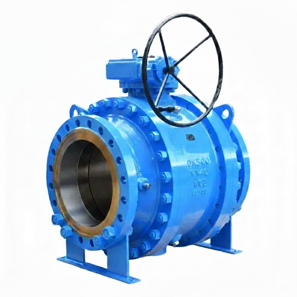
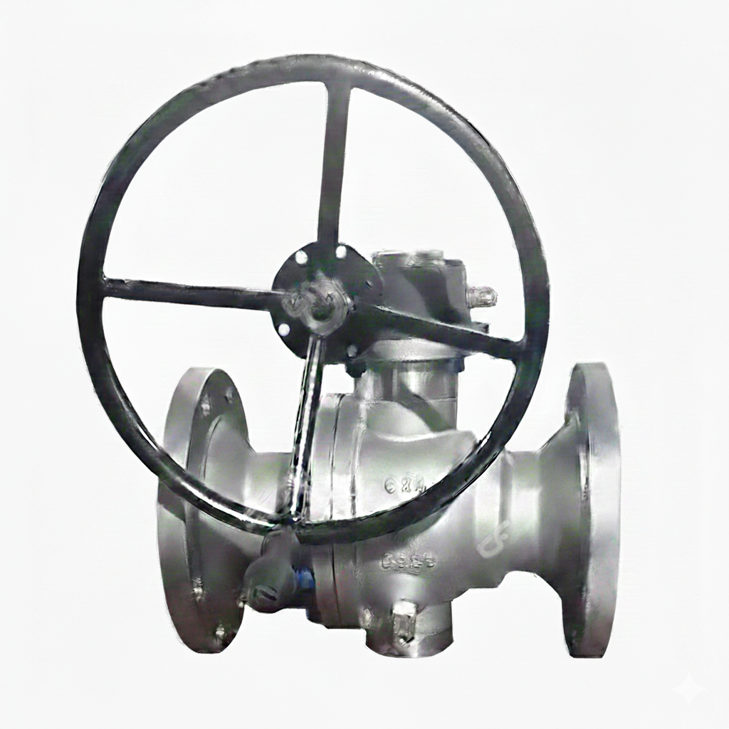
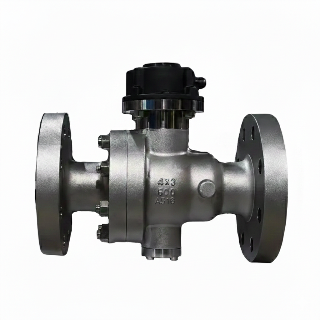
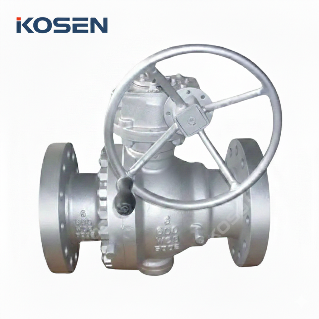
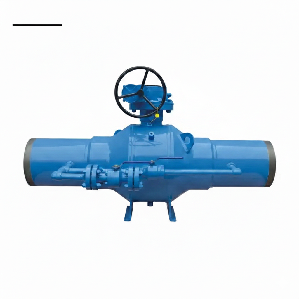
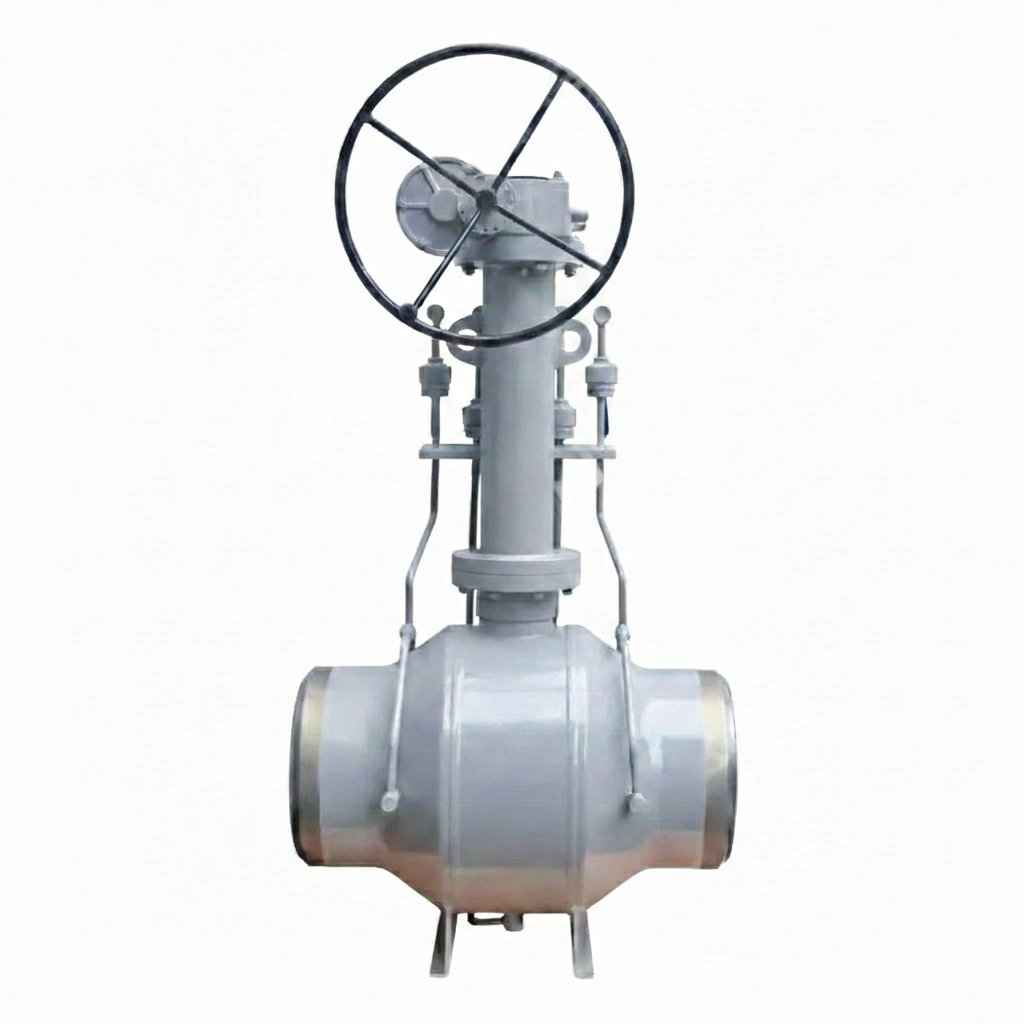
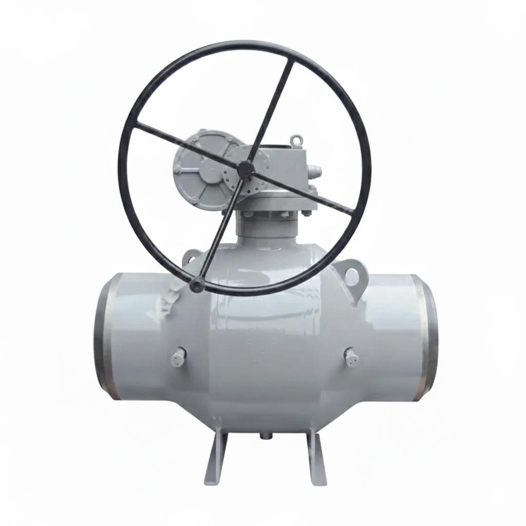
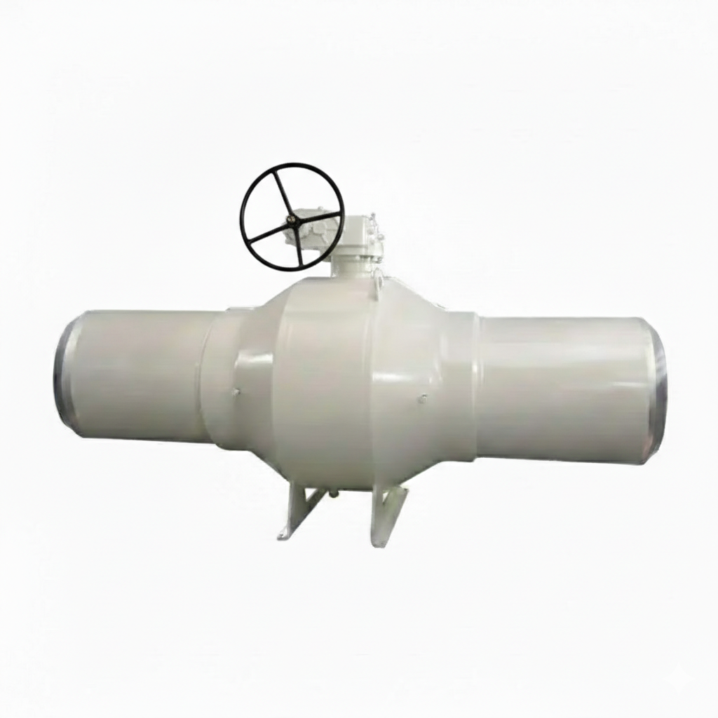
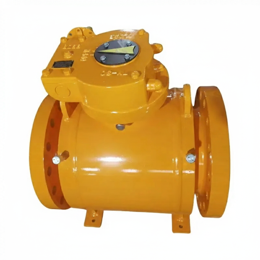
The Custom Fully Welded Ball Valve Factory specializes in producing versatile Trunnion Mounted Ball Valves with a Side Entry design. These valves adhere to the stringent API 6D standards, ensuring reliability and performance. They are fully customizable in terms of material, size, and pressure rating to meet specific customer requirements. The valves feature RF (Raised Face) flanged ends for secure connections and come equipped with a gearbox for smooth and efficient operation.
Model No.: KV-20250612-FWBV-02
Hits: 17
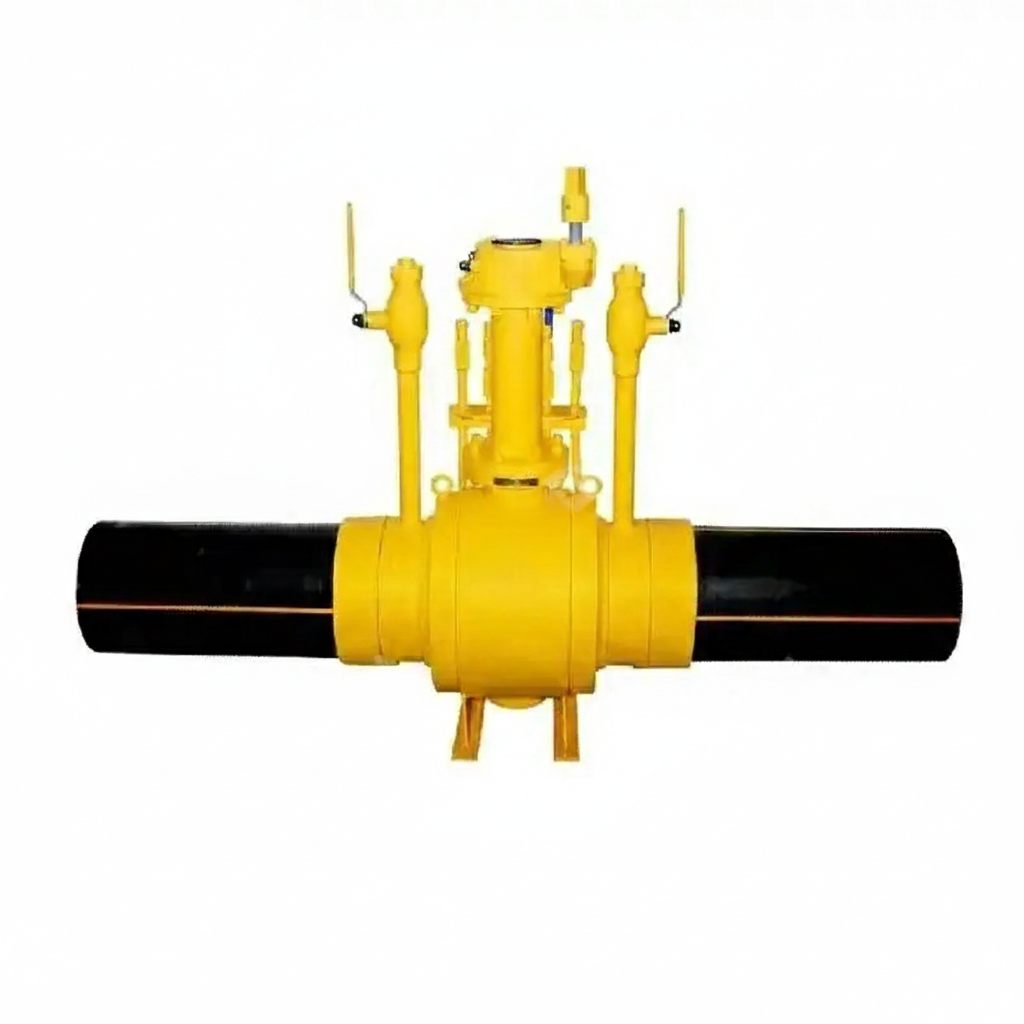
The Directly Buried Fully Welded Ball Valve Plant offers robust and reliable valves designed for underground applications. These valves comply with API 6D standards and feature a forged carbon steel ASTM A105 body, ensuring durability and strength. They come with extended polyethylene (PE) pipes for direct burial, eliminating the need for above-ground casings. Customized options are available to meet specific requirements. The valves are equipped with a gearbox for easy operation and feature a butt weld connection for seamless integration into pipelines.
Model No.: KV-20250612-FWBV-01
Hits: 27
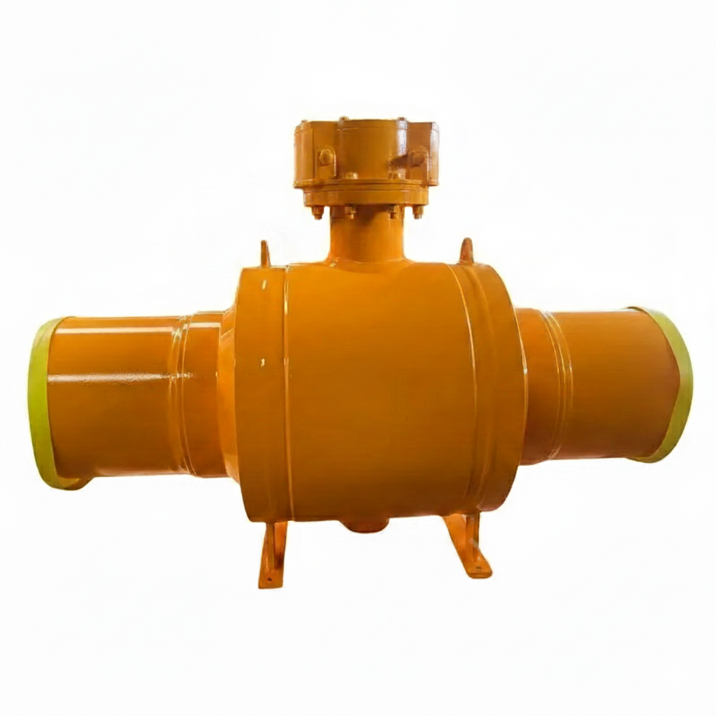
Customized Fully Welded Ball Valve Plant offers a versatile solution with trunnion-mounted design and extended body, tailored to meet specific customer requirements. The valves are available in various materials, sizes, and pressure ratings, ensuring compatibility with diverse applications. Each valve is equipped with butt-welded (BW) ends for secure and seamless integration into piping systems.
Model No.: KV-20250528-FWBV-02
Hits: 40
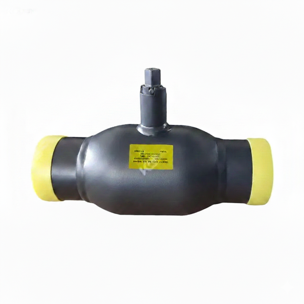
The Heating Integrated Ball Valve from our supplier is a fully welded ball valve, designed to meet the stringent standards of API 6D. It features an ASTM A105 forged carbon steel body, ensuring durability and reliability. The valve is available in a DN150 size, equivalent to 6 inches, with a pressure rating of PN16 and Class 150 LB. It is equipped with butt-welded (BW) ends for seamless integration into piping systems.
Model No.: KV-20250528-FWBV-01
Hits: 25
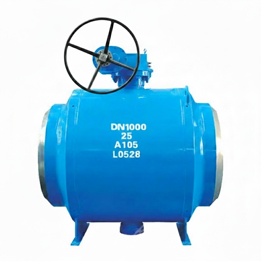
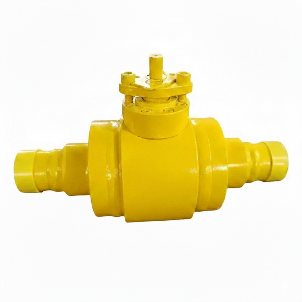
The High Pressure Fully Welded Ball Valve is engineered to meet API 6D standards, featuring a robust carbon steel ASTM A105 body for superior strength and durability. With customizable sizes and pressure ratings, it offers flexible solutions for various applications. The valve is equipped with butt welded ends for secure connections and operates via a reliable lever mechanism, ensuring efficient control of high-pressure fluid systems.
Model No.: KV-20250224-FWBV-01
Hits: 30
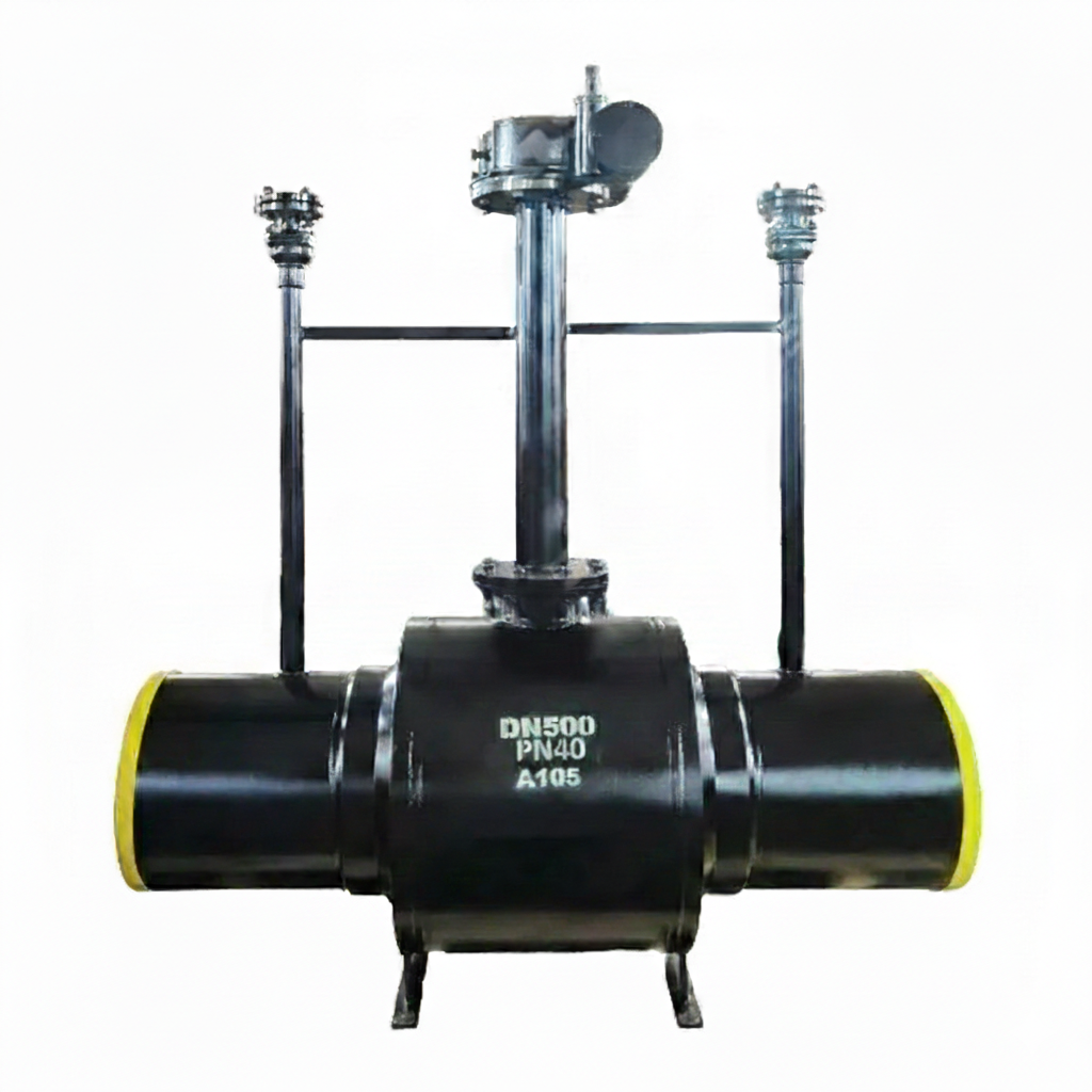
The Underground Fully Welded Ball Valve Supplier offers high-quality ball valves designed in accordance with API 6D standards. These valves feature a durable carbon steel body made from ASTM A105 material, ensuring strength and reliability. Available in a large DN500 (20-inch) size, they are rated for PN40 and Class 300 LB pressure classes. The valves come with butt-welded ends for secure and efficient installation.
Model No.: KV-20250220-FWBV-01
Hits: 27
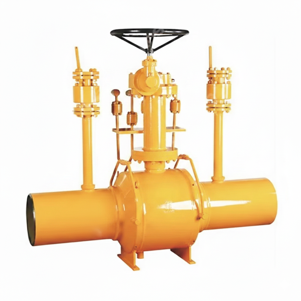
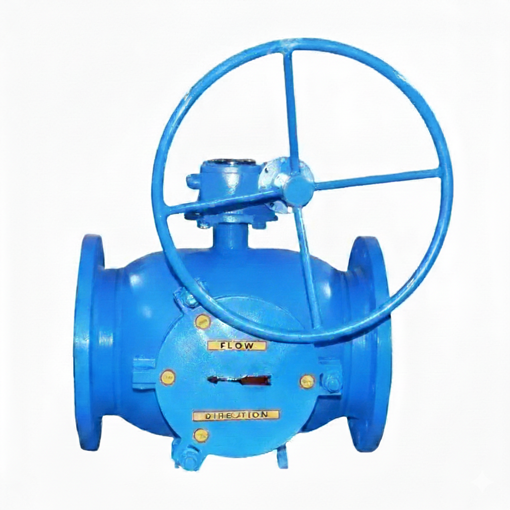
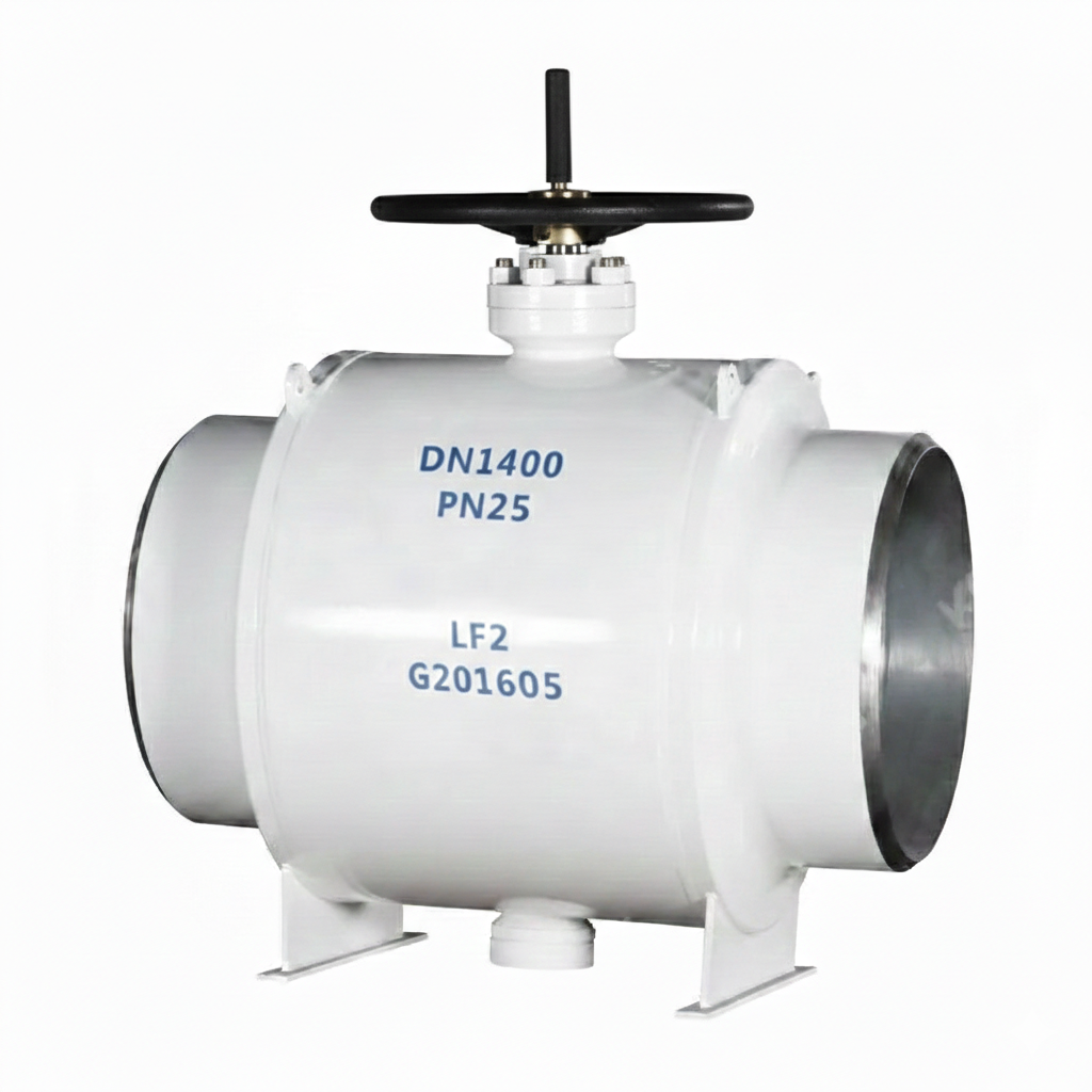
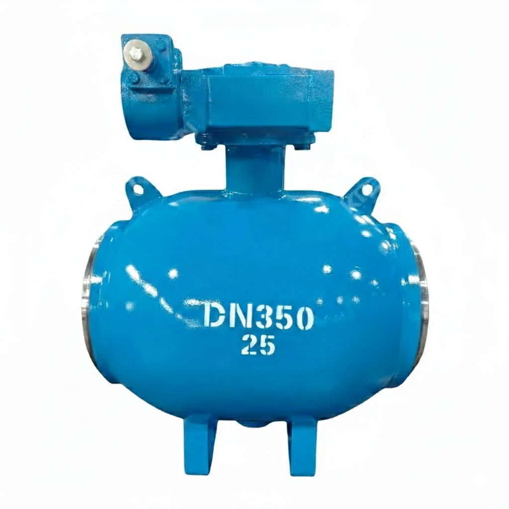
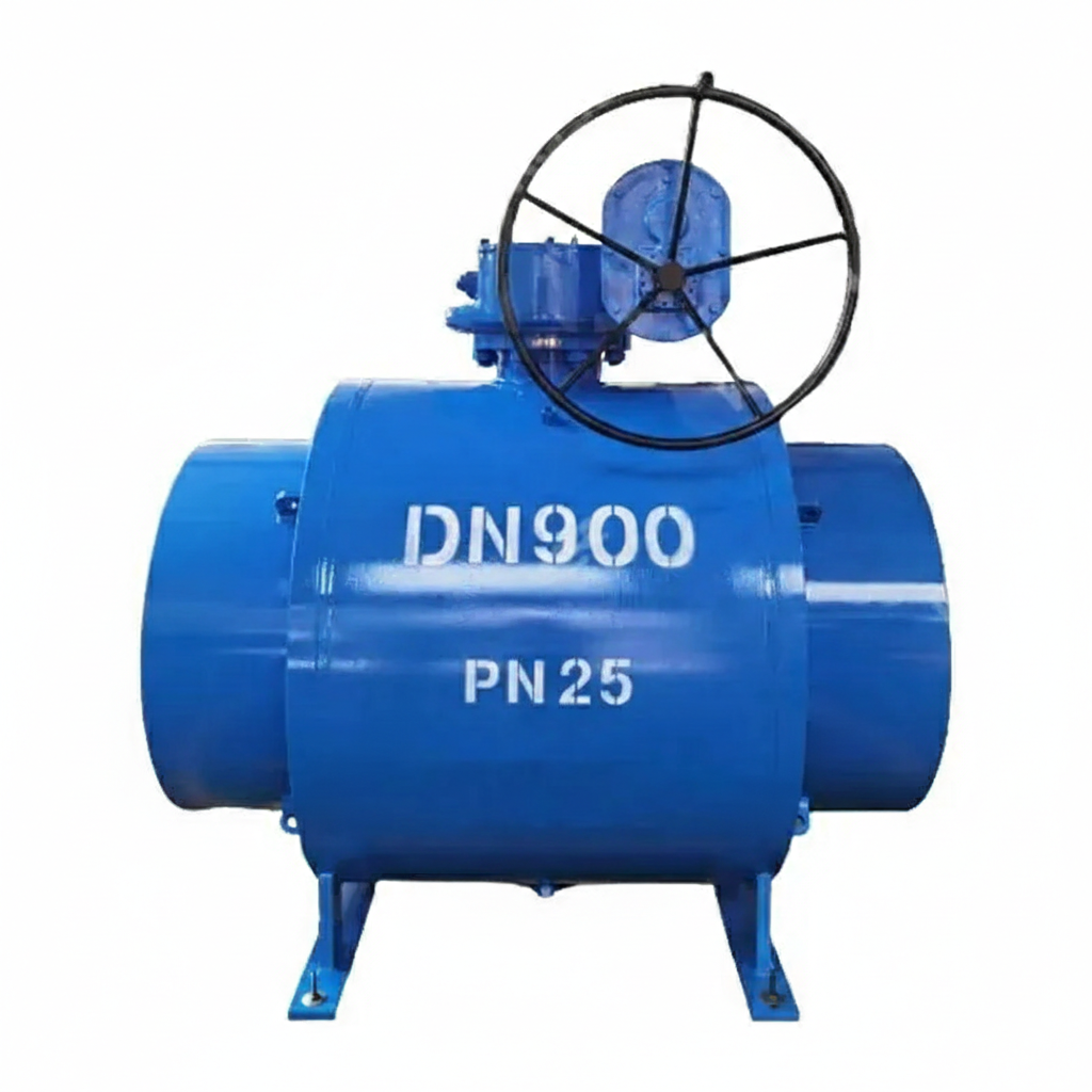
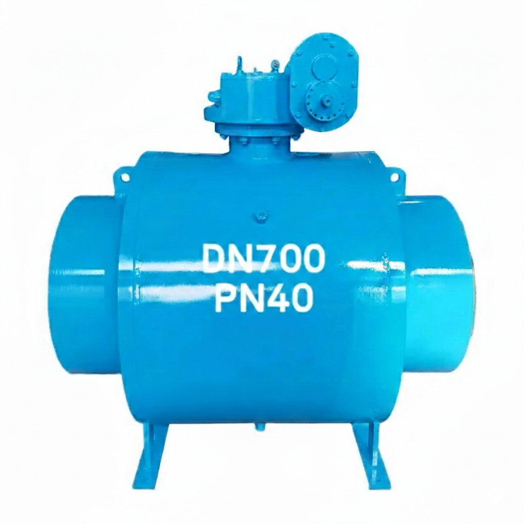
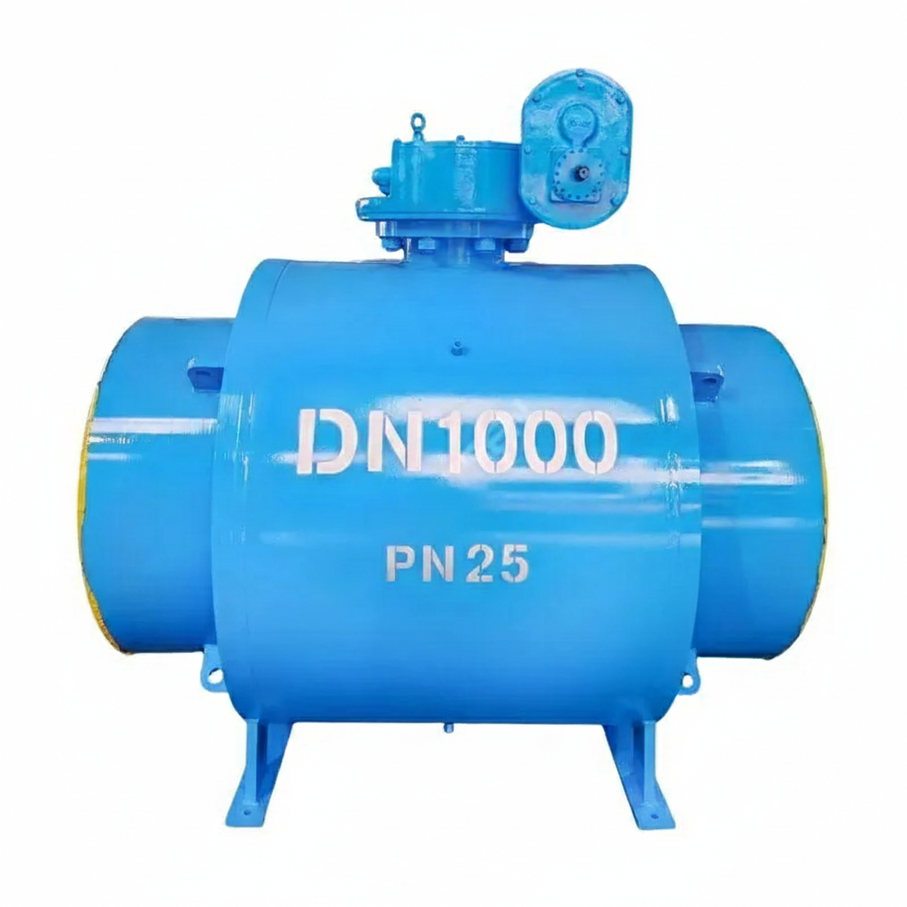
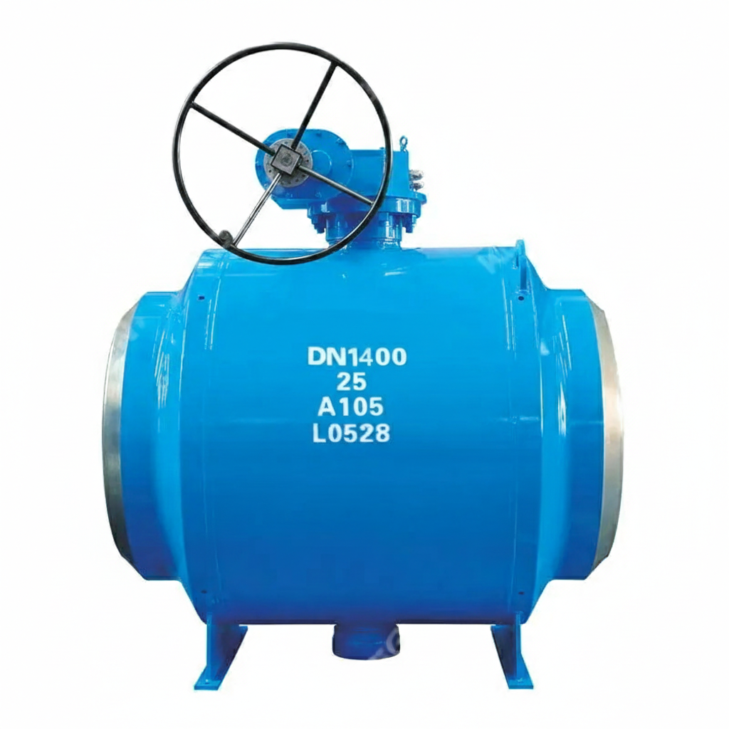
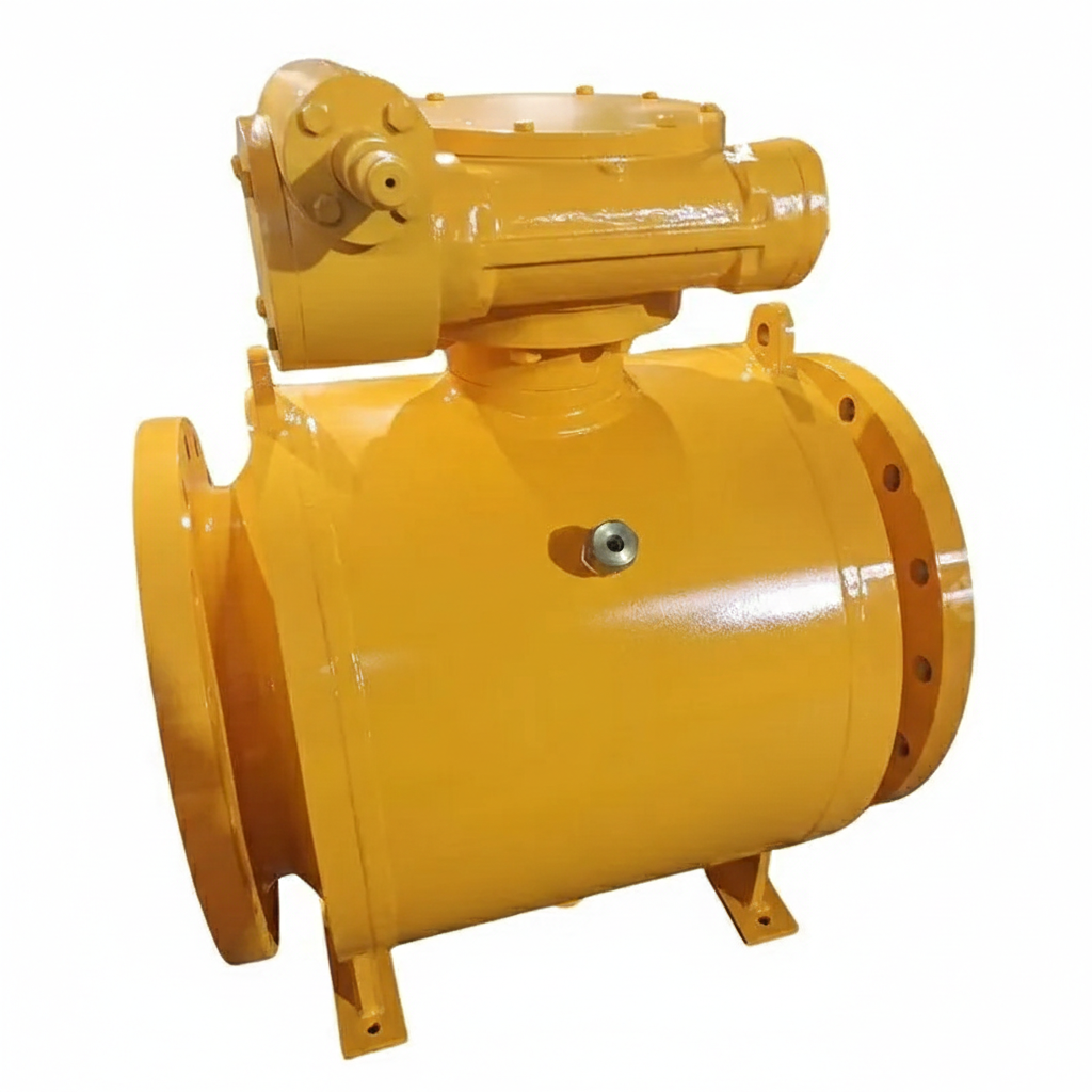
This ASTM A105 Fully Welded Ball Valve, designed according to API 6D standards, features a carbon steel body for strength and durability. It is available in customized sizes with a Pressure Class 300 LB rating and RF flanged ends, ensuring secure and efficient operation in various industrial applications.
Model No.: KV-20241231-FWBV-02
Hits: 66
Self-priming mobile pump Tanker with a gasoline or diesel engine for pumping light petroleum products: gasoline, kerosene, light heating oil. These mobile pumps are designed to meet customer needs and offer performance levels between the Tanker 150 and Tanker 049 mobile pumps. This mobile pump is ideal for field work and for use in off-site power outages. Its light weight and two-wheel chassis make this self-priming mobile pump mobile and easy to transport around the site. The pump frame and chassis are manufactured from high-quality steel of optimal thickness using high-precision laser cutting machines, ensuring durability and longevity. This mobile pump utilizes self-priming pumps designed for pumping light petroleum products. These pumps offer unique characteristics such as a self-priming lift of up to 7 meters and a pressure of up to 30 meters, along with excellent efficiency. Thanks to its powerful and compensated engine, this light petroleum product mobile pump boasts excellent hydraulic performance. The engine is easy to operate and has a proven track record. The belt drive prevents direct contact between the pump and the mobile, preventing possible product heating. Antistatic belts and balanced cast iron pulleys, made in Germany, offer an extended service life and increased power transfer efficiency.
Applications
Standby pump for pumping fuel at oil depots, petroleum product warehouses, and gas stations (during accidents and power outages) while maintaining safety;
Pumping petroleum products from tanks and reservoirs into tank trucks or emergency storage tanks;
Unloading light petroleum products from tank trucks or railcars in the field;
use as a backup pump for a fuel tanker, which can be installed above the frame level (independent diesel pump for fuel tankers, fuel trucks) in the event of failure of the main pump (in off-road conditions, the power take-off shaft is often damaged).